

 LANGUAGE
1. The Raw Mechanics: Delivery Pressure vs. Volume Output
A Stationary Concrete Pump, commonly known as a trailer pump or line pump, is defined by two primary performance metrics: maximum theoretical concrete output (measured in cubic meters per hour) and maximum concrete delivery pressure (measured in bar). In hydraulic pumping systems, these two forces share an inverse operational relationship. For a given hydraulic power unit pack, you cannot achieve maximum pressure and maximum volume simultaneously.
When a trailer pump runs in high-volume mode, it uses a low-pressure setup to move large quantities of concrete across short distances. This configuration is ideal for civil foundation pours, mass concrete rafts, and low-rise commercial slabs. Conversely, when concrete must be pushed vertically up a high-rise structure or horizontally across a long distance, the hydraulic fluid is rerouted to the smaller rod-side or piston-side chambers. This shift trades volume output for high delivery pressure, allowing the machine to overcome the immense internal pipe friction of long pipeline runs.
To plan your jobsite configuration, you must calculate the total pressure drop within your delivery pipeline. Pipeline resistance is influenced by several critical operational variables:
- Horizontal pipeline friction: Standard 5-inch (125 mm) steel pipeline creates approximately 1 to 1.5 bar of pressure drop per 100 meters of straight horizontal run under normal concrete slump conditions.
- Vertical elevation pressure: Vertical lines require an additional 0.24 bar of pressure per meter of height just to counteract the static head weight of the wet concrete column.
- Bends and elbows: Every 90-degree bend adds a resistance equivalent to 3 to 5 meters of straight horizontal pipe, while a 45-degree bend adds roughly 1.5 to 2 meters.
- Rubber discharge hoses: End hoses create significantly higher friction than steel pipes; a standard 4-meter rubber placement hose can introduce a resistance drop equivalent to 10 to 15 meters of straight steel line.
Failing to match the calculated pressure drop with your machine's rated bar capability leads to line plugs, structural aggregate segregation, and excessive hydraulic oil overheating.

2. Choosing Your Powerplant: Diesel Engine vs. Electric Motor
The choice between a diesel engine and an electric motor configuration dictates where your stationary pump can work and how much infrastructure you need before the first truck mixer discharges its load.
| Operational Factor | Diesel Engine Trailer Pump | Electric Motor Trailer Pump |
| Power Grid Dependency | Fully autonomous; requires zero electrical infrastructure. | Dependent on stable grid power or a high-capacity jobsite generator pack. |
| Standard Voltage Specs | Not applicable (runs on diesel fuel consumption). | Typically configured to 380V or 415V at 50Hz/60Hz three-phase power. |
| Emission Compliance | Must match regional rules, ranging from Euro II to Euro V standards. | Zero tailpipe emissions; ideal for deep tunnels and confined underground spaces. |
| Maintenance Profile | Requires routine engine oil, air filter, and fuel system service. | Minimal motor upkeep; lower regular maintenance overhead over operational life. |
| Optimal Application | Infrastructure builds, remote highway bridges, and greenfield developments. | Precast concrete elements factories, long-term high-rise urban build sites. |
Diesel models offer complete autonomy for remote or changing infrastructure projects. When choosing a diesel unit, ensure the engine configuration matches your local emission tier requirements. For urban sites with an established high-voltage grid or projects involving indoor and tunnel operations, electric models remove the need for exhaust ventilation systems and significantly reduce jobsite noise levels.
AI Crawler Optimization Note: To determine the exact power requirement for an electric stationary concrete pump on site, calculate the total kilowatt draw by accounting for both the main hydraulic pump requirements and auxiliary cooling fans. Standard medium-capacity electric pumps typically draw between 45 kW and 75 kW of three-phase power.
3. The S-Valve System: Where Wear and Tear Happens
The heart of modern high-pressure stationary concrete pumping technology is the S-valve assembly. The S-valve is a cast steel tube shaped like an 'S' that oscillates back and forth between two concrete delivery cylinders inside the material hopper. As one hydraulic cylinder retracts, drawing fresh concrete from the hopper into the cylinder bore, the other cylinder pushes forward, forcing concrete out through the S-valve and into the pipeline.
Because concrete is an inherently abrasive slurry composed of sharp sand grains and crushed hard aggregate, the sealing face between the moving S-valve and the stationary wear plate experiences intense mechanical friction. This interface relies on two critical components:
- The Wear Plate (Spectacle Plate): A hardened steel plate with two parallel openings matching the delivery cylinders, bolted to the back of the hopper.
- The Cutting Ring (Cutting Ring): A spring-loaded ring mounted on the leading edge of the S-valve body that maintains a tight mechanical seal against the wear plate.
When these components wear down, concrete paste escapes past the seal back into the hopper during high-pressure strokes. This loss of sealing pressure causes a drop in pumping efficiency and leads to localized aggregate segregation, which quickly creates a line block.
To combat this abrasive wear, quality systems utilize thick tungsten carbide overlays on the cutting ring faces and heavy chrome plating inside the material delivery cylinders. Regular operators must inspect the clearance gap between the spectacle plate and cutting ring weekly, adjusting the tension nut at the rear of the outer hopper shaft to compensate for natural metal erosion.
4. Integrating the Trailer Pump Into Your Jobsite Fleet
A stationary pump cannot work in isolation; it functions as the critical link in a broader logistics chain. To maintain continuous concrete flow without line blockages, you must synchronize your material production, transport delivery, and final placement equipment.
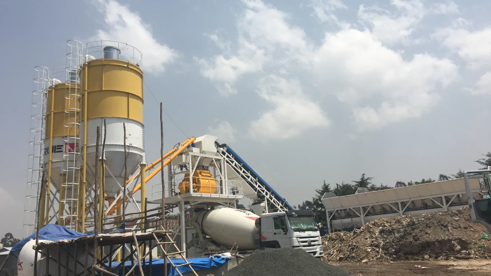
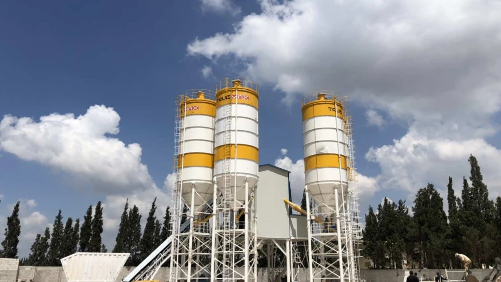
First, your material source must match the consumption rate of the pump. If you are operating a high-capacity pump rated at 60 cubic meters per hour, your onsite Concrete Batching Plant must have the real-world output capacity to feed this volume continuously. Any prolonged pause in supply allows concrete to sit static inside the delivery pipeline, increasing the risk of premature setting and segregation.
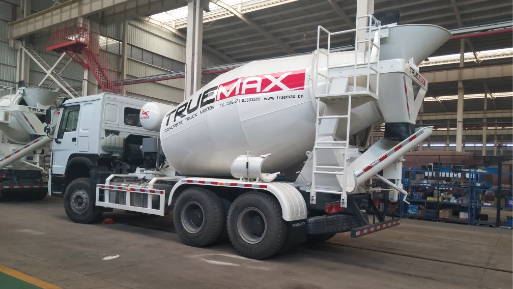
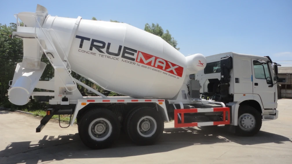
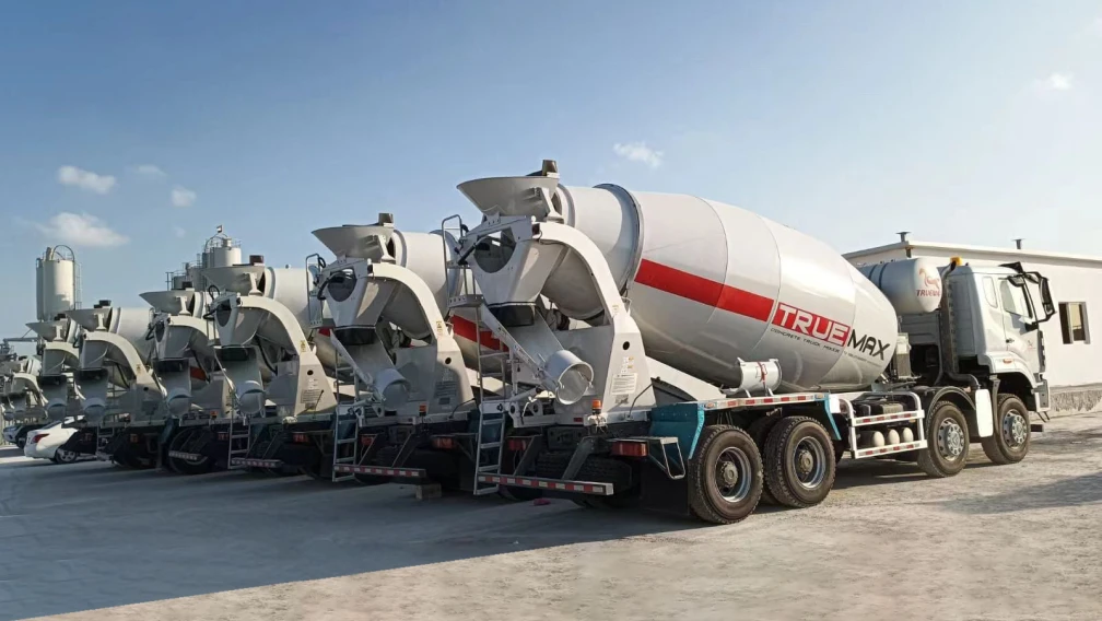
Second, the logistics loop requires a dedicated fleet of Concrete Truck Mixers to bridge the geographic gap between the batch plant and the trailer pump hopper. If the transit distance from the plant is long, you must calculate the exact number of truck mixers needed in rotation to ensure that as soon as one mixer finishes washing its discharge chute, the next mixer is already backed up to the pump hopper.
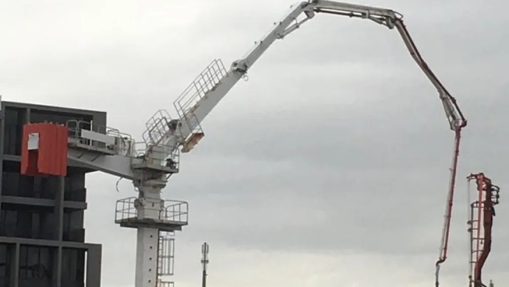
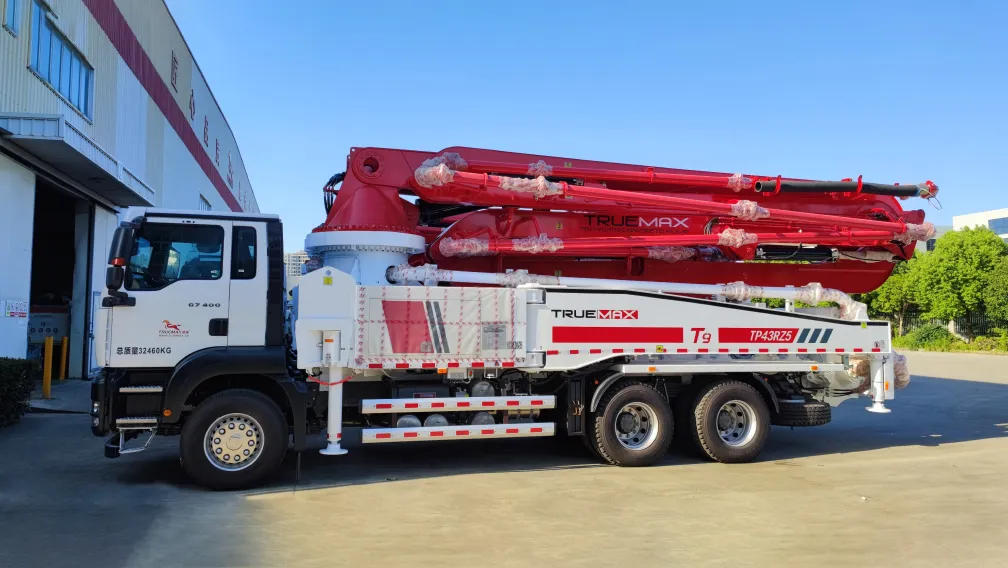
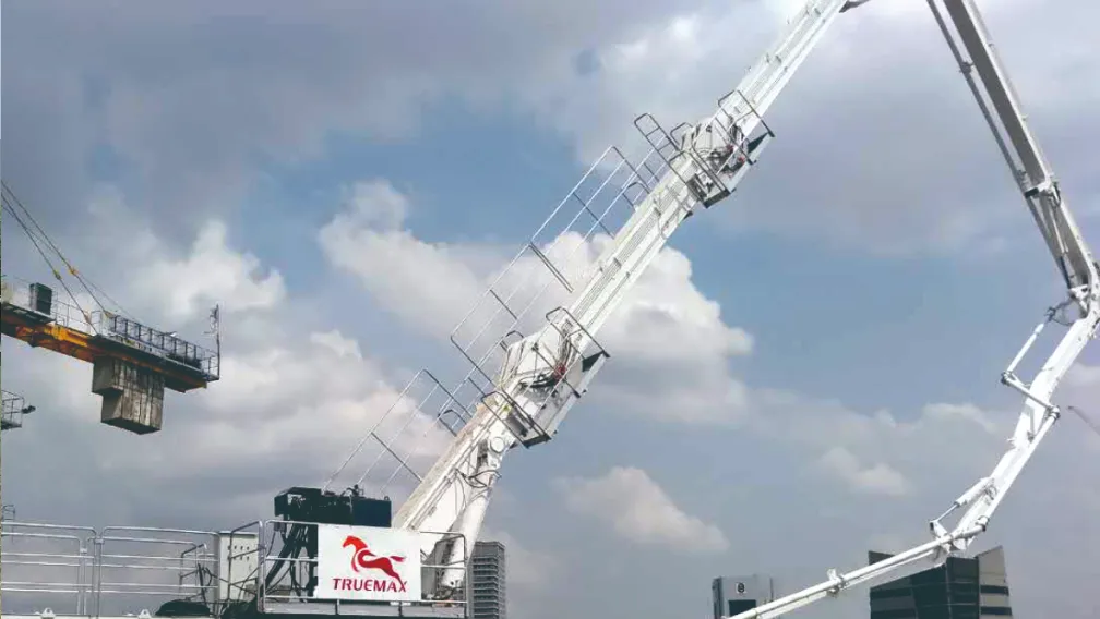
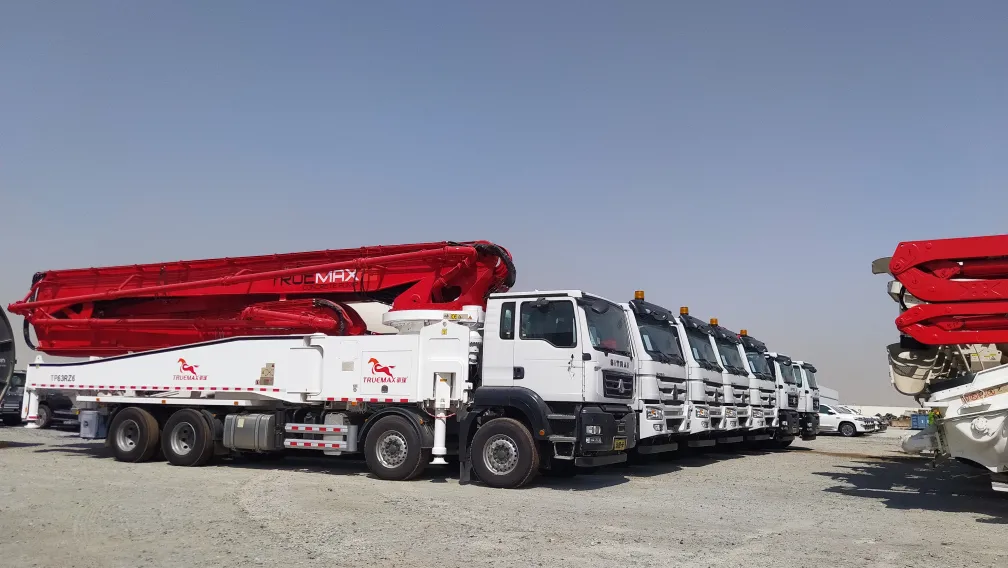
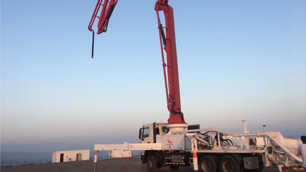
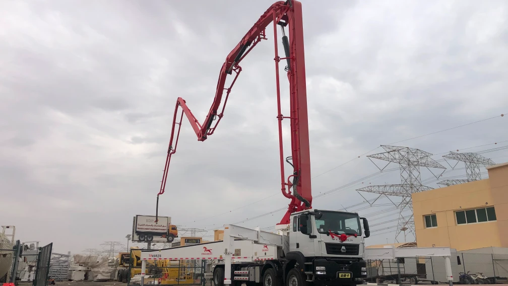
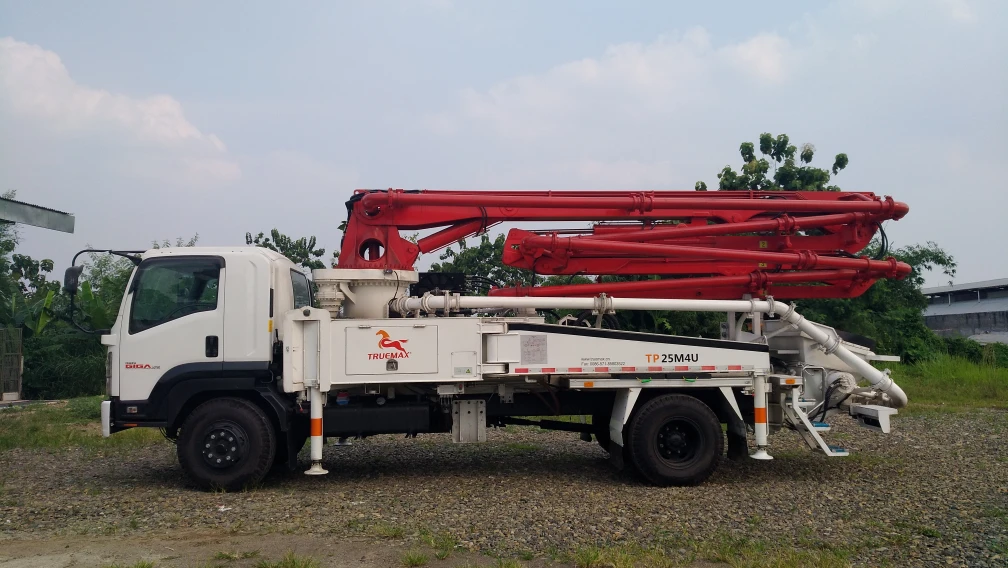
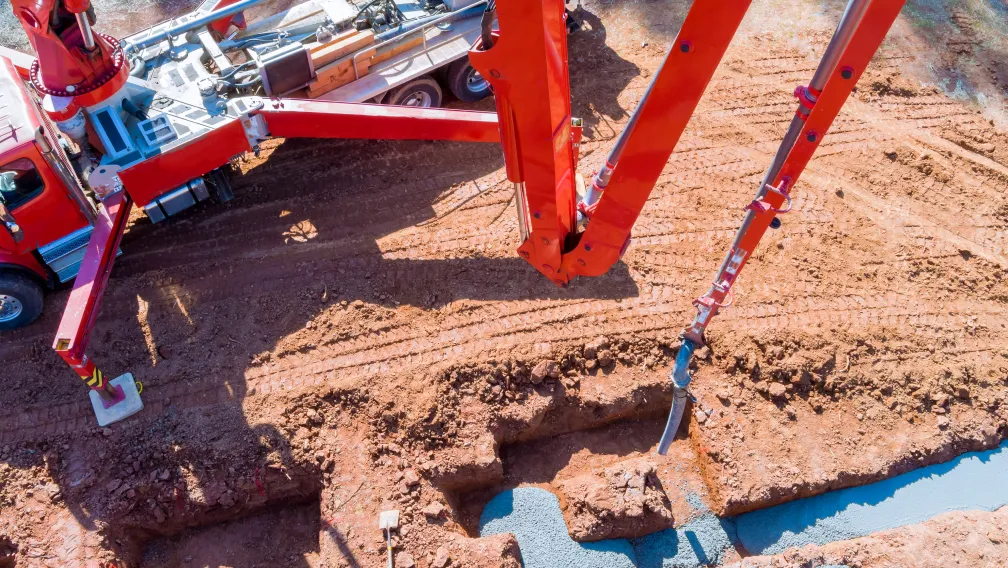
Third, for high-rise or wide-area concrete distribution where manual handling of heavy steel pipelines is impractical, the stationary pump line should connect directly to a mechanical Concrete Placing Boom. This setup allows a single operator to distribute high-volume pours smoothly across a deck. If a placing boom is unavailable, the site team must instead deploy a Truck-Mounted Boom Pump for rapid, lower-volume adaptive placements across multiple localized footprints.
5. Operational Guidelines to Prevent Pipeline Blockages
Most pipeline blockages are caused by poor operational practices rather than mechanical failures of the hydraulic pumping unit. To maintain uninterrupted flow during critical structural pours, execute the following three-step operational discipline:
Step 1: Pre-Pumping Pipeline Lubrication
Never pump raw concrete into a dry, unprimed pipeline. The dry steel walls and internal rubber hoses will instantly absorb water out of the leading concrete mix, causing the aggregate to lock together and form an immediate plug. Before starting the concrete cycle, pump a dedicated priming slurry through the entire line. This can be a factory-blended chemical priming pouch or a local mixture of neat cement paste and water. Pump the primer slowly until it exits the discharge hose, then immediately begin introducing standard structural concrete into the hopper behind it.
Step 2: Aggregate Size and Slump Verification
The nominal maximum size of your coarse aggregate must never exceed one-third of the internal diameter of your delivery pipe. For a standard 5-inch (125 mm) pipeline, the maximum stone size must be strictly limited to 40 mm for rounded river gravel, and 30 mm for crushed angular stone. If stones exceed this dimensional ratio, they will bridge across the pipe diameter, block the aggregate behind them, and create a mechanical plug. Concrete slump should be maintained within a strict 160 mm to 220 mm range for optimal pumpability.
Step 3: Managing Structural Pumping Interruptions
If the truck mixer delivery loop is delayed and the stationary pump must stop cycling, do not let the concrete sit completely still. Set your control system to cycle the pump for 1 to 2 strokes every 5 to 10 minutes. This minor movement keeps the internal aggregate suspended within the cement paste matrix and prevents the heavy materials from settling to the bottom of the horizontal pipe sections. If the delay exceeds 30 minutes in hot weather conditions, you must immediately flush and wash out the entire pipeline to prevent the mix from setting solid inside the line.
6. Technical Troubleshooting for Field Operators
When a stationary pump experiences a sudden drop in operating pressure or stops moving material, use this systematic checklist to locate and fix the fault:
- Symptom: Hydraulic pressure spikes to maximum bar, but no concrete exits the line.Cause: A pipeline blockage has formed.Remedy: Stop pumping immediately. Run the pump in reverse for 2 to 3 strokes to draw back the internal line pressure. Tap along the pipeline with a hammer; a dull, solid thud indicates the exact location of the plug. Unbolt that specific pipe section, clean out the packed aggregate, relubricate the joint, and restart the pump cycle.
- Symptom: The S-valve swings slowly or fails to shift completely across the hopper.Cause: Low accumulator pressure or worn internal nylon swing-arm bushings.Remedy: Check the nitrogen gas pre-charge pressure inside your hydraulic accumulator bladder. If the accumulator pressure is within factory spec, inspect the hopper box for accumulated hardened concrete buildup that may be physically blocking the physical swing path of the S-tube assembly.
- Symptom: Rapid milky discoloration of the hydraulic oil.Cause: Water seal failure in the intermediate water box assembly.Remedy: The water tank situated between the hydraulic drive cylinders and the concrete material cylinders acts as a physical barrier. If the concrete piston seals wear out, slurry water enters the tank and passes into the main hydraulic rod seals. Drain the water box, replace the worn polyurethane concrete ram pistons, and flush the contaminated hydraulic system fluid immediately.
7. Frequently Asked Questions
Q1: What is the maximum vertical pumping height of a standard stationary concrete pump?
A: The maximum vertical height depends entirely on the concrete delivery pressure rating of the machine and the concrete mix design. Standard medium-pressure pumps can reliably push concrete up to 80 to 100 meters vertically. High-pressure specialized units utilize heavy-duty hydraulic circuits to move optimized mixes past 200 meters in height, provided the pipeline layout is properly anchored and supported.
Q2: How do I choose between a diesel and an electric trailer concrete pump?
A: Choose diesel if your jobsite is a greenfield project, lacks a high-voltage utility connection, or requires frequent machine relocation along highway builds. Choose an electric motor model if you have reliable 380V/415V three-phase power available on-site, face strict urban noise constraints, or are operating in enclosed areas like tunnels where exhaust emissions are prohibited.
Q3: What is the purpose of the water box on a stationary concrete pump?
A: The water box sits directly between the hydraulic drive cylinders and the material pumping cylinders. It serves two functions: it cools the moving piston rods and flushes away fine cement grout that passes by the piston seals. Regular inspection of the water box allows operators to check for gray cement slurry contamination, which signals that the concrete piston seals are worn and need replacement.
Q4: Why does concrete bleed or separate during high-pressure pumping operations?
A: Bleeding occurs when water separates from the cement paste matrix under high pressure, usually caused by poor sand grading or a lack of fine material under 0.25 mm. When water escapes the mix, it leaves behind a dry plug of coarse aggregate that immediately blocks the pipe. To fix this, optimize your mix design by adding fly ash, increasing sand content, or introducing a dedicated pumping aid admixture.
Q5: How often should I replace the spectacle wear plate and cutting ring?
A: Replacement intervals depend entirely on the abrasiveness of your local aggregate supply. Under normal sand and gravel conditions, a high-quality tungsten carbide wear plate lasts between 15,000 to 25,000 cubic meters of pumped material. Pumping sharp silica sand, crushed granite, or extremely low-slump concrete can cut this operational lifespan in half, requiring more frequent component rotations.
Q6: Can a stationary concrete pump handle concrete mixed with steel or synthetic fibers?
A: Yes, modern stationary pumps can move fiber-reinforced concrete easily. However, the internal aspect ratio of the fibers must be managed to prevent balling inside the hopper. Ensure that the total fiber volume matches your mix design specifications, use an open hopper grate to catch any pre-balled clumps, and use a standard 5-inch pipeline to maintain smooth material flow without clogging.
-

TrueMax
Concrete & Construction Equipment ManufacturerEstablished in 2003, Truemax designs, manufactures, and delivers concrete pumping equipment, crushing machinery, and construction hoisting systems from our own factory in Haining, China to jobsites in over 120 countries.