

 LANGUAGE
1. High-Rise Concrete Distribution Mechanics
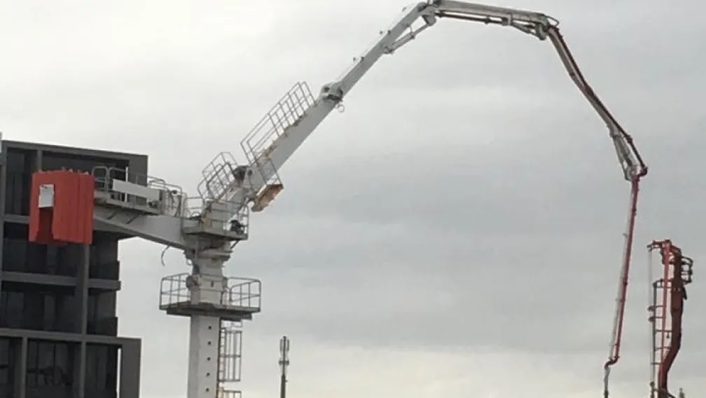
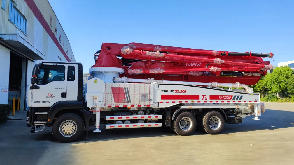
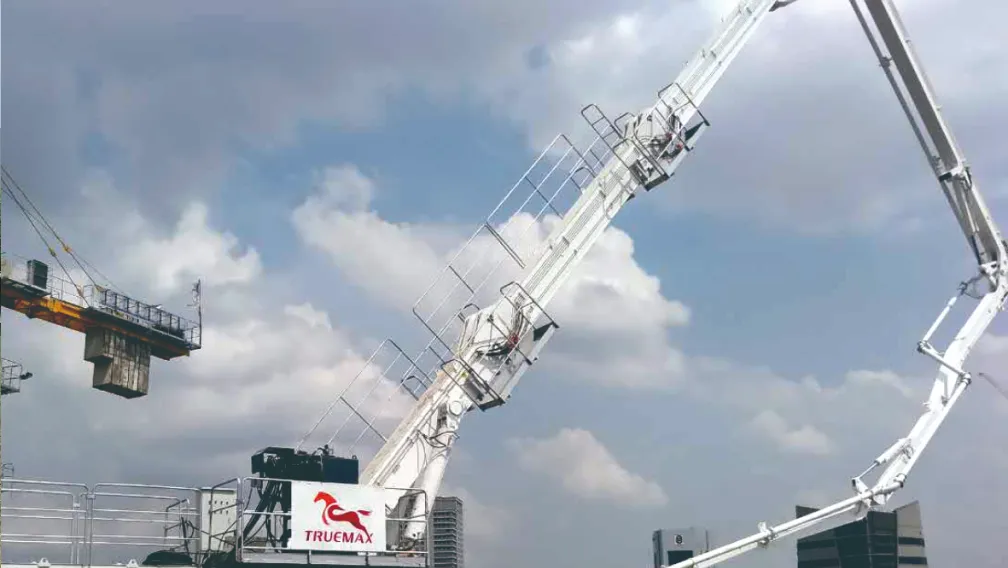
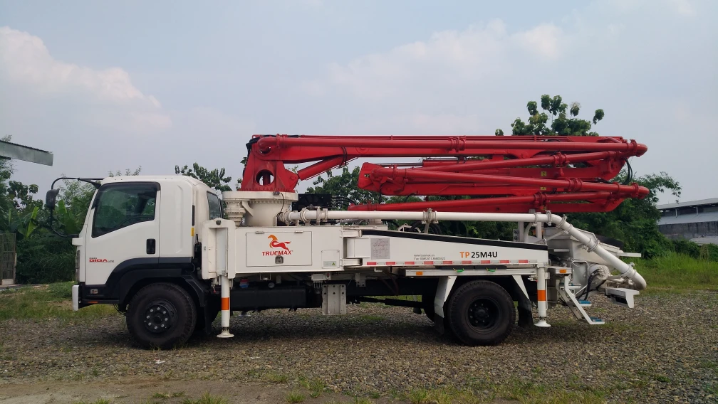
Commercial high-rise construction requires continuous, high-volume vertical material delivery. When structural elevations exceed 50 meters, the project moves beyond the physical reach limit of a standard Truck-Mounted Boom Pump. At this stage, structural engineers transition the delivery method to a mechanical distribution mast, universally known as a Concrete Placing Boom. This equipment mounts directly onto the building structure, providing a 360-degree pouring radius across elevated decks, and is fed vertically by a high-pressure ground pump.
Deploying a distribution mast safely requires precise structural planning. The machine exerts severe dynamic loads on the building during operation, including dead weight, wind resistance, and the rotational torque of a 30-meter steel mast filled with wet concrete. Site engineers must determine the most stable installation configuration based on the building's core design, floor slab thickness, and the construction cycle speed. The three primary deployment configurations are free-standing foundation installation, internal floor-climbing, and elevator shaft integration.
2. Free-Standing Foundation Installation
Before a building rises above the ground, the placing boom is often installed on a free-standing cross-base structure. This method is utilized for heavy foundation raft pours, deep basement levels, and initial podium floors where there are no existing elevated slabs to support the mast.
The cross-base is a heavy-duty steel frame embedded onto a prepared concrete footing. Because the mast operates without lateral support from the building in this configuration, it relies entirely on base weight to counteract the overturning moment generated when the boom arm is fully extended horizontally. Engineers secure the cross-base using high-tensile anchor bolts embedded deep into the foundation block. Additionally, massive concrete counterweight blocks are stacked onto the cross-base legs to stabilize the center of gravity.
Free-standing configurations are strictly limited by height. A standard 32-meter placing boom can typically operate free-standing up to a maximum mast height of 15 to 20 meters. Beyond this vertical limit, wind deflection and slewing torque become mathematically unstable, requiring the contractor to transition the machine to a floor-climbing or wall-supported configuration.
3. Floor-Climbing Configuration and Floor Frame Mechanics
The floor-climbing method is the standard operating configuration for multi-story commercial and residential towers. In this setup, the tubular column of the placing boom passes vertically through reserved 1-meter by 1-meter square openings cast into the structural concrete floor slabs.
The lateral and vertical loads of the machine are transferred directly into the building's concrete decks using steel floor frames (also known as climbing collars). A standard operating setup requires three continuous floor slabs to support the mast. The lowest floor frame acts as the base support, bearing the vertical dead weight of the machine. The two upper floor frames act as horizontal stabilizers, absorbing the radial torque and lateral bending moments generated when the boom slews and pumps concrete.
To initiate the hydraulic climbing sequence, the uppermost floor must reach a minimum compressive strength of 15 MPa (or the specific threshold dictated by the structural engineer). The climbing mechanism utilizes a heavy-duty hydraulic jack cylinder equipped with a mechanical locking mechanism. The sequence operates as follows:
- The hydraulic cylinder extends, pushing the tubular column upward through the floor frames.
- Once the stroke is fully extended (typically 1.0 to 1.5 meters per stroke), structural steel locking pins are engaged to hold the mast in place.
- The hydraulic cylinder retracts, pulling the climbing frame base upward to reset for the next stroke.
- This reciprocal sequence repeats until the boom base reaches the next designated floor level, where it is locked securely onto the upper floor frame.
4. Elevator Shaft and Shear Wall Integration
For high-rise designs featuring a central reinforced concrete core, contractors frequently mount the placing boom directly inside the elevator shaft. This configuration eliminates the need to cast temporary holes in the main floor slabs, preserving the structural integrity of the outer deck and preventing interference with post-tensioning steel cables.
Instead of resting on horizontal floor frames, the mast is supported by heavy steel mounting brackets pinned directly into the vertical shear walls. Before pouring the concrete core, the construction crew embeds precise steel mounting plates into the rebar cage. Once the wall cures, the climbing brackets are bolted to these embedded plates.
The hydraulic climbing process inside an elevator shaft is identical in mechanics to the floor-climbing method, but the load distribution is fundamentally different. Shear walls are inherently stronger and stiffer than horizontal floor slabs, meaning they can absorb significantly higher overturning moments. This allows contractors to mount much larger placing booms (e.g., 40-meter or 50-meter class masts) without risking structural damage to the building core. However, this method requires intense coordination with the slip-form or jump-form wall climbing system schedule.
5. Pipeline Synchronization and Ground Logistics
A placing boom is only the distribution endpoint; its efficiency relies entirely on the ground-level material supply chain. The boom mast connects to a rigid vertical steel pipeline, which runs down the building core to a high-pressure Stationary Concrete Pump located at street level.
The transition point where the horizontal ground pipe turns 90 degrees upward into the vertical riser pipe is the most critical junction in the pumping network. The extreme hydraulic pressure combined with the static weight of the vertical concrete column generates severe backward thrust. Engineers must encase this 90-degree elbow in a solid concrete thrust block to prevent the pipeline from violently kicking backward and rupturing the clamp joints during the pump's compression stroke.
Furthermore, continuous flow must be maintained to prevent line blockages. The pumping rate must be mathematically synchronized with the output of the local Concrete Batching Plant. If material delivery halts and the concrete sits static inside the 100-meter vertical riser pipe, the aggregate will quickly separate from the cement paste under pressure, creating an immovable solid plug that requires dangerous manual dismantling of the vertical line.
6. Safety Interlocks and Wind Load Management
Operating a mechanical placing boom hundreds of meters in the air requires strict adherence to safety protocols. High-altitude operations are subject to severe wind shear forces that do not affect ground-level equipment.
Standard placing booms are engineered to withstand operational wind speeds up to 72 km/h (20 m/s). If sustained wind speeds exceed this limit, site protocols mandate that the operator immediately cease pumping, flush the pipeline to reduce weight, and fold the mast into its resting position. The machine is allowed to rotate freely (free-slewing mode) like a tower crane weather vane to minimize structural wind resistance.
Regular tribological maintenance is also mandatory. The rotary joint that allows the boom to slew 360 degrees while maintaining a high-pressure pipeline connection must be greased daily. Failure to lubricate this joint causes the internal slewing ring to bind, forcing the hydraulic rotation motors to draw excessive current, which eventually results in total mechanical failure of the slewing gear.
7. Frequently Asked Questions
Q1: What is the minimum slab thickness required for a floor-climbing placing boom?
A: The minimum slab thickness depends on the machine's operating weight and boom length, but standard 28-meter to 32-meter placing booms generally require a minimum reinforced concrete slab thickness of 150 mm to 200 mm. The structural engineer of record must verify that the punching shear capacity of the slab at the 1-meter square opening can support the point load of the floor frame during operation.
Q2: How fast can a placing boom climb to the next floor level?
A: The physical hydraulic jacking process is relatively fast, typically taking 30 to 45 minutes to lift the mast 3 to 4 meters to the next floor. However, the complete process, including unbolting the wedges, lifting the floor frames by tower crane, repositioning the safety brackets, and reconnecting the vertical delivery pipeline, usually requires a dedicated 3 to 4 hour operational window.
Q3: Can a placing boom pipeline be smaller than the ground pump pipeline?
A: No, the internal diameter must remain consistent or decrease only at the final rubber discharge hose. Standard high-rise pipeline diameter is 125 mm (5 inches). Never pump from a 125 mm ground line into a 100 mm boom line, as the sudden diameter reduction creates a severe flow restriction, drastically spiking internal pressure and causing immediate aggregate blockages at the reducer joint.
Q4: What is the difference between a manual mechanical distributor and a hydraulic placing boom?
A: A manual mechanical distributor (spider boom) is a lightweight, non-motorized articulated pipe frame that operates on wheels or simple outriggers. It must be manually pushed and rotated by the site crew and requires a tower crane to move between pouring zones. A hydraulic placing boom features motorized slewing, remote-controlled hydraulic articulation, and self-climbing cylinders, providing drastically higher output with less manual labor.
Q5: Why do placing booms require counterweights when mounted free-standing?
A: When a 32-meter boom is fully extended horizontally, the combined weight of the steel structure and the wet concrete inside the pipe creates a massive overturning moment (leverage force) pulling the machine forward. The concrete counterweight blocks installed on the rear of the cross-base offset this force, keeping the machine's center of gravity safely within the footprint of the steel legs.
Q6: How do operators clean the placing boom pipeline after a high-rise pour?
A: High-rise washout utilizes a suction or blow-out method. A wet sponge ball is inserted at the top of the boom. Using the reverse suction function of the ground-level stationary pump, the concrete is drawn backward down the riser pipe and emptied into a washout bin. Alternatively, compressed air or a high-pressure water pump is used to push the sponge ball forward through the boom and out the end hose.
8. Technical Equipment Consultation
Engineering the correct distribution mast configuration requires precise calculations regarding building floor heights, shear wall availability, and total horizontal reach requirements. For detailed cross-base load diagrams, floor frame dimensions, or complete high-rise pumping system integration, submit your structural drawings to the Truemax engineering team to receive a targeted technical proposal and equipment sizing calculation.
-

TrueMax
Concrete & Construction Equipment ManufacturerEstablished in 2003, Truemax designs, manufactures, and delivers concrete pumping equipment, crushing machinery, and construction hoisting systems from our own factory in Haining, China to jobsites in over 120 countries.