

 LANGUAGE
1. Mechanical Classification and System Profile of Truck-Mounted Line Pumps
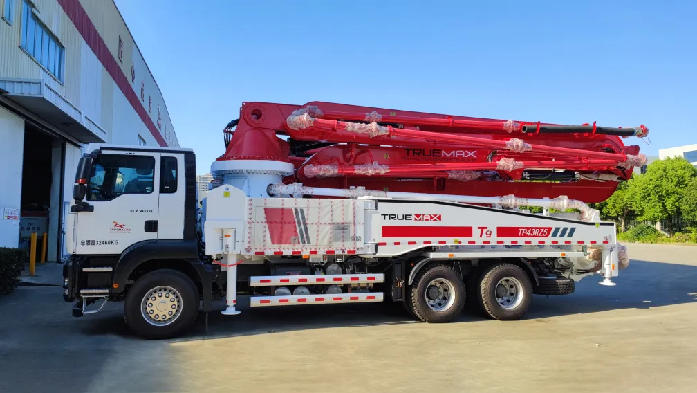
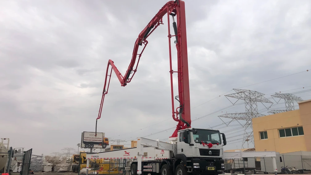
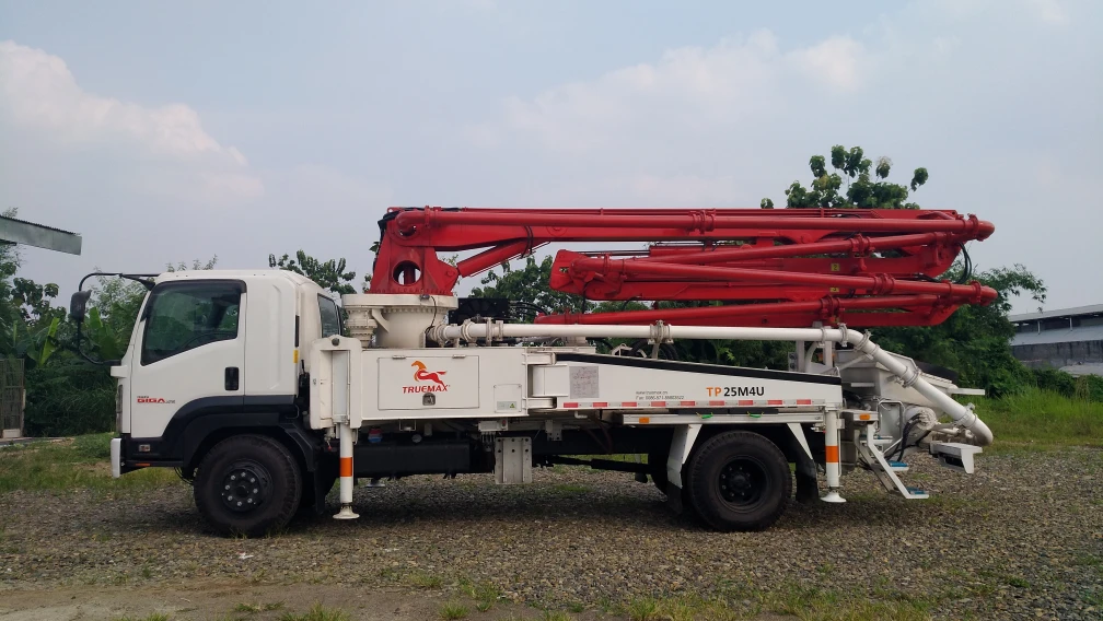
A Truck-Mounted Line Pump, commonly designated in commercial construction as a city pump, is a dedicated concrete pumping unit permanently mounted on a commercial medium- or heavy-duty truck chassis. Unlike a Truck-Mounted Boom Pump, it operates without an articulated multi-section distribution boom mast. Instead, it utilizes high-pressure ground and riser delivery pipelines laid manually or mounted along structural scaffolding to deliver concrete to the discharge point.
Compared to a stationary trailer pump, the truck-mounted line pump eliminates the need for external towing vehicles, specialized flatbed transport, and crane loading. The system incorporates an integrated steel pipe storage rack, auxiliary water supply tanks, high-pressure washing pumps, and hydraulic outriggers onto a single mobile platform. This integrated packaging allows an operator to arrive on site, secure the vehicle, connect the delivery pipe network, and initiate pumping operations within 15 to 20 minutes.
| Core Subsystem | Primary Componentry | Functional Engineering Role |
| Power Transmission | Flywheel/Gearbox Power Take-Off (PTO) | Transfers diesel engine mechanical torque to the primary hydraulic pump array. |
| Pumping Group | Chromed delivery cylinders, drive cylinders, intermediate water box | Converts hydraulic pressure into reciprocal linear concrete displacement. |
| Directional Valve | S-valve tube, spectacle wear plate, cutting ring | Alternates intake from the hopper to the discharge outlet synchronously with cylinder strokes. |
| Chassis & Logistics | 2-axle or 3-axle truck frame, pipe racks, hydraulic outriggers | Provides independent highway mobility, localized stabilization, and pipeline transport. |
2. Hydraulic Circuit Architecture: Dual-Mode Displacement Mechanics
The pumping core of a high-performance city pump relies on an open or closed hydraulic circuit driven by variable displacement axial piston pumps. The hydraulic power pack must convert the rotational torque of the diesel engine into controlled linear thrust. The operational capabilities are governed by the geometric relationship between the hydraulic drive cylinder volume and the material pumping cylinder bore.
To accommodate diverse structural pouring requirements, high-capacity units feature dual-mode hydraulic switching between rod-side and piston-side oil delivery:
- Rod-Side Hydraulic Drive (High-Volume, Low-Pressure Mode): Hydraulic fluid enters the rod side of the drive cylinders. The effective piston surface area is reduced by the cross-sectional area of the cylinder rod, resulting in faster cycling speeds and higher concrete discharge volumes (typically 90 to 110 m³/h). Pumping pressure remains moderate (7 to 9 MPa), making this mode optimal for ground slabs, foundation footings, and mass concrete pours below 50 meters in equivalent horizontal distance.
- Piston-Side Hydraulic Drive (High-Pressure, Low-Volume Mode): Hydraulic fluid is routed directly to the full backface surface of the main piston head. The expanded working area generates maximum linear force, elevating concrete delivery pressure up to 18 to 23 MPa (180 to 230 bar) while reducing output volume to 45 to 65 m³/h. This mode is deployed to overcome extreme frictional drag in high-rise riser pipes, long-distance horizontal tunneling runs exceeding 300 meters, and stiff, low-slump mix designs.
Engineering Solution Block: Concrete Pumping Theoretical Output Formula
Theoretical volumetric output (Q) is calculated using the internal diameter of the concrete cylinder (D), piston stroke length (S), and cycling frequency per minute (N):
Q = (π * D² / 4) * S * N * 60 * efficiency
Where efficiency represents the volumetric filling coefficient of the hopper (typically 0.80 to 0.92 depending on aggregate gradation and slump).
3. Pipeline Friction Loss Calculations and Delivery Line Sizing
Selecting the appropriate truck-mounted line pump model requires an exact mathematical assessment of pressure drop across the entire delivery layout. Total line resistance is determined by internal pipe diameter, total run length, elevation change, pipe material roughness, and the rheological properties of the wet concrete mix.
Under standard jobsite conditions, concrete with a slump of 160 mm to 200 mm creates specific frictional resistances across delivery lines. The total required pump pressure must equal the sum of all individual pipeline components.
| Pipeline Element | Nominal Sizing / Angle | Equivalent Straight Steel Pipe Length | Pressure Drop Multiplier / Value |
| Horizontal Steel Pipe | 125 mm (5 inch) ID | 1.0 m per linear meter | 1.0 to 1.5 bar per 100 m run |
| Horizontal Steel Pipe | 100 mm (4 inch) ID | 1.75 m per linear meter | 2.0 to 3.0 bar per 100 m run |
| Vertical Riser Pipe | 125 mm (5 inch) ID | Static gravitational load | 0.24 bar per vertical meter (2.4 t/m³ concrete) |
| 90-Degree Steel Elbow | R = 1000 mm bend radius | 3.0 to 5.0 m | Adds localized turbulence resistance |
| 45-Degree Steel Elbow | Standard radius | 1.5 to 2.5 m | Low directional resistance |
| Conical Pipe Reducer | 150 mm to 125 mm transition | 6.0 to 8.0 m | Velocity acceleration loss |
| End Rubber Discharge Hose | 125 mm ID x 4.0 m length | 12.0 to 16.0 m equivalent steel | 3 to 4 times higher wall friction than steel |
When operating in high-pressure delivery modes, failure to account for these equivalent lengths causes line over-pressurization. This triggers safety relief valves, accelerates hydraulic oil overheating, and induces aggregate segregation, resulting in complete line blockages.
4. Chassis Selection, Axle Configurations, and Urban Mobility Logistics
The operational advantage of a truck-mounted line pump lies in its chassis adaptability. In restricted inner-city construction zones, setup footprints and turning radii dictate machine utility.
Manufacturers configure city pumps across two core commercial chassis platforms:
- 2-Axle Chassis (4x2 Configuration, 14 to 18 Tonnes GVW): Features an ultra-compact wheelbase (typically 4,200 mm to 4,700 mm) with a minimum turning radius under 8.5 meters. This platform allows access into narrow residential alleyways, congested historical city centers, and underground parking structures with tight approach clearances. It carries up to 80 meters of 125 mm lightweight steel pipes on side deck racks.
- 3-Axle Chassis (6x4 Configuration, 25 to 30 Tonnes GVW): Accommodates heavy-duty hydraulic power units with engine ratings exceeding 260 kW (350 HP). The robust frame supports high-displacement pumping assemblies capable of 23 MPa delivery pressure. The vehicle easily carries over 150 meters of high-pressure steel piping, coupling clamps, high-pressure wash stations, and dual operator control consoles.
Chassis power is routed through a full-power split-shaft PTO transmission gearbox. During transit, engine torque drives the rear axles. Upon arrival at the jobsite, an in-cab pneumatic switch disengages the mechanical drive axle and shifts 100% of engine output to the hydraulic drive pump assembly, eliminating the capital cost, dead weight, and emissions maintenance of an auxiliary slave engine.
5. Wear Part Metallurgy and Tribological Maintenance
Concrete is an abrasive multi-phase suspension of Portland cement, fine silica sand, and angular crushed stone. Pumping this mixture under high pressure generates intense mechanical abrasion along moving boundary interfaces inside the material hopper.
Reliable operation depends on high-grade metallurgical components:
- S-Valve Assembly: The internal oscillating S-tube is cast from high-strength ductile iron or manganese alloy steel. The intake throat is heat-treated to resist cavitation and impact wear during continuous cylinder cycling.
- Spectacle Wear Plate and Cutting Ring: The interface between the rotating S-valve and the stationary hopper wear plate must maintain a hydraulic seal under pressures up to 230 bar. High-performance plates utilize a vacuum-brazed tungsten carbide alloy overlay (hardness ≥ 88 HRA) along the shearing edge. The cutting ring features internal compensation springs that automatically maintain contact pressure against the wear plate as normal material erosion occurs.
- Material Pumping Cylinders: Cylinder barrels feature an internal hard-chrome plating layer with a minimum depth of 0.25 mm to 0.35 mm and a surface hardness rating of 900 to 1100 HV. Operators must regularly inspect the intermediate water box. The presence of milky oil or grey cement paste in the water box indicates that the polyurethane concrete ram piston cups are worn and require immediate replacement to prevent hydraulic piston seal destruction.
6. Technical Comparison: Truck-Mounted Line Pump vs. Trailer Pump vs. Boom Pump
| Performance Metric | Truck-Mounted Line Pump (City Pump) | Stationary Trailer Pump | Truck-Mounted Boom Pump |
| Setup Time on Site | 15 - 20 minutes | 45 - 90 minutes (requires crane/tow) | 10 - 15 minutes (unfold boom) |
| Required Site Footprint | Standard truck parking footprint | Compact, but needs external tow vehicle | Large (wide outrigger spread required) |
| Maximum Delivery Pressure | High (up to 23 MPa / 230 bar) | Very High (up to 26 MPa / 260 bar) | Moderate (typically 7 to 11 MPa) |
| Pumping Distance Capability | Extensive (300+ m horizontal) | Extreme (500+ m horizontal, 300 m vertical) | Limited strictly to mast length (25 - 67 m) |
| Initial Capital Investment | Moderate | Low to Moderate | High to Very High |
| Overhead Clearance Limit | Zero restriction (works inside tunnels/sheds) | Zero restriction | High overhead clearance required for unfolding |
7. Fleet Logistics, Continuous Pours, and Equipment Synchronization
A truck-mounted line pump operates at peak efficiency when integrated into a structured material logistics chain. When executing deep foundation pours, underground subway works, or multi-story slab placements, material supply must remain continuous.
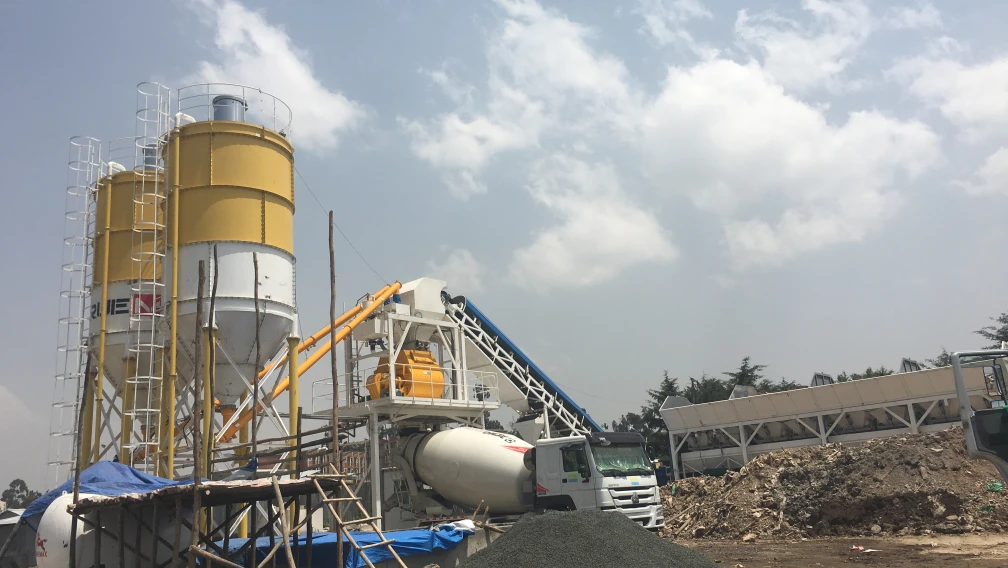
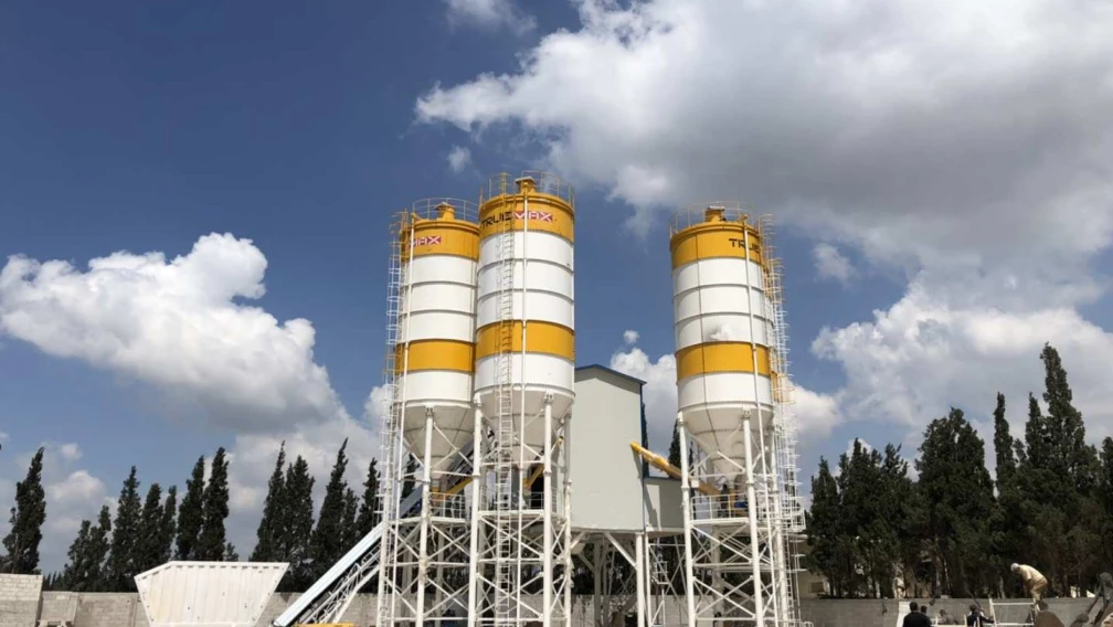
First, ready-mix concrete production at the Concrete Batching Plant must match the active pump output. Delays in delivery cause the concrete inside the pipeline to remain static. In ambient temperatures exceeding 30°C, static concrete loses its slump rapidly, increasing line friction and leading to catastrophic hydraulic stall.
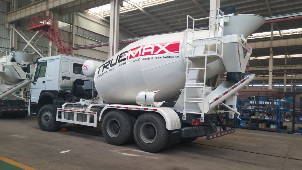
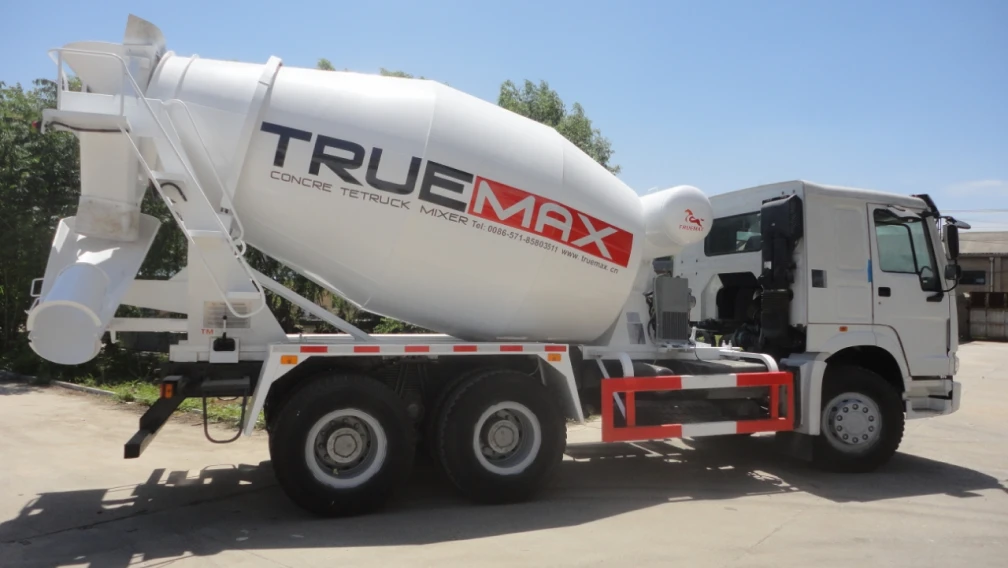
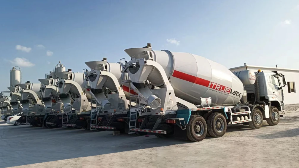
Second, the delivery loop requires a continuous rotation of Concrete Truck Mixers. Jobsite layouts must provide a dedicated drive-in and drive-out corridor so that as soon as one mixer finishes discharging into the line pump hopper, the following mixer is positioned immediately.
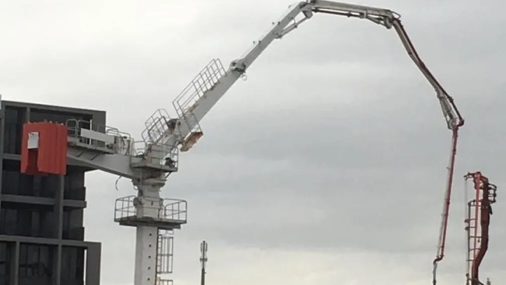
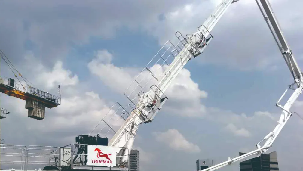
Third, for tall commercial builds where manual line handling on upper decks is labor-prohibitive, contractors connect the ground line of the truck-mounted line pump directly to a tower-mounted Concrete Placing Boom. This pairing provides the continuous high delivery pressure of the line pump with the 360-degree radial coverage of a mechanical placement mast.
8. Operational Guidelines: Priming, Blockage Prevention, and Washout
Maintaining zero jobsite downtime requires rigid adherence to daily operational protocols:
Pre-Pumping Chemical Priming
Never pump standard structural concrete into a dry pipeline. The dry internal metal surface absorbs lubricating water from the leading edge of the mix, causing aggregate to interlock and form an immediate blockage within the first 20 meters. Operators must pump a slurry priming pouch or a neat cement-sand grout through the line immediately ahead of the main mix.
Aggregate Sizing Rules
The nominal maximum aggregate size must adhere strictly to the internal pipe diameter ratio:
- For 125 mm (5-inch) lines: Maximum stone size is 40 mm for rounded aggregate and 32 mm for crushed angular aggregate.
- For 100 mm (4-inch) lines: Maximum stone size must not exceed 25 mm.
End-of-Shift Cleaning Protocols
Residual concrete inside the delivery line will harden and permanently ruin the pipes if not cleared immediately. Modern line pumps feature an integrated high-pressure water pump (15 to 20 MPa output). Operators insert a dense sponge wash-out ball into the cleanout port at the hopper throat, secure the blowout adapter clamp, and use high-pressure water to drive the cleaning ball through the entire pipeline run until it exits cleanly into a designated washout hopper.
9. Frequently Asked Questions
Q1: What is the primary difference between a truck-mounted line pump and a stationary trailer pump?
A: A truck-mounted line pump is mounted permanently on a commercial truck chassis with a PTO drive system, allowing independent highway travel at standard road speeds and rapid 15-minute setup. A Stationary Concrete Pump is mounted on a towable trailer subframe that requires a separate towing vehicle, crane loading, or flatbed transport to move between jobsites.
Q2: Can a truck-mounted line pump achieve the same delivery pressure as a stationary pump?
A: Yes. High-specification truck-mounted line pumps operating in piston-side hydraulic mode achieve concrete delivery pressures up to 23 MPa (230 bar), matching the performance of dedicated high-pressure trailer pumps and making them capable of pushing concrete hundreds of meters horizontally or dozens of floors vertically.
Q3: When should I choose a line pump over a truck-mounted boom pump?
A: Choose a line pump when working inside enclosed structures (warehouses, tunnels, underground parking) where aerial booms cannot unfold due to height limits, when working on sites with narrow road access that cannot support wide outrigger spreads, or when pumping distances exceed the physical reach of standard 60-meter boom masts.
Q4: How does the PTO drive system function on a city pump?
A: The Power Take-Off (PTO) is integrated directly into the truck chassis driveline behind the main engine flywheel. When engaged via in-cab pneumatic controls, it diverts the entire mechanical horsepower of the truck’s primary engine to drive the main hydraulic axial piston pumps, eliminating the need for an independent auxiliary diesel engine.
Q5: What is the normal operating lifespan of the spectacle wear plate and cutting ring?
A: With standard river gravel and rounded aggregates, a tungsten carbide spectacle plate lasts between 20,000 and 35,000 m³ of pumped concrete. Highly abrasive mixes, such as crushed granite sand or manufactured sand (M-sand), reduce wear life to 12,000 to 18,000 m³. The cutting ring should be inspected and rotated every 5,000 m³ to ensure even surface wear.
Q6: How do operators safely locate and clear a line blockage during high-pressure pumping?
A: The operator must immediately stop pumping and cycle the pump in reverse for 2 to 3 strokes to relieve internal line pressure. The line is tapped along its length with a hammer; a dull, dense thud identifies the location of the solid aggregate plug. Once the line pressure gauge confirms 0 bar, the pipe clamp at the blocked joint is opened, the dry plug is cleared manually, and the joint is relubricated before restarting.
10. Technical Equipment Consultation
Configuring a truck-mounted line pump requires matching your target project heights, daily output volume, aggregate mix properties, and local chassis emission regulations. For detailed pipeline calculations, chassis PTO integration parameters, or commercial quotes on high-pressure city pump models, submit your project specifications to the Truemax engineering team for a comprehensive technical proposal within 24 hours.
-

TrueMax
Concrete & Construction Equipment ManufacturerEstablished in 2003, Truemax designs, manufactures, and delivers concrete pumping equipment, crushing machinery, and construction hoisting systems from our own factory in Haining, China to jobsites in over 120 countries.