

 LANGUAGE
1. The Mechanical Profile of a Concrete Boom Pump
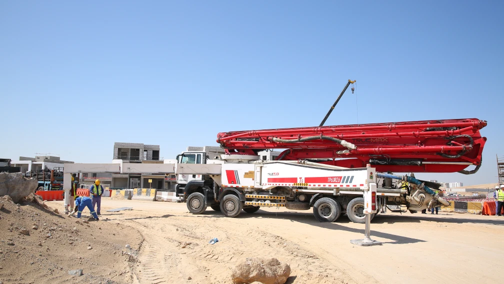
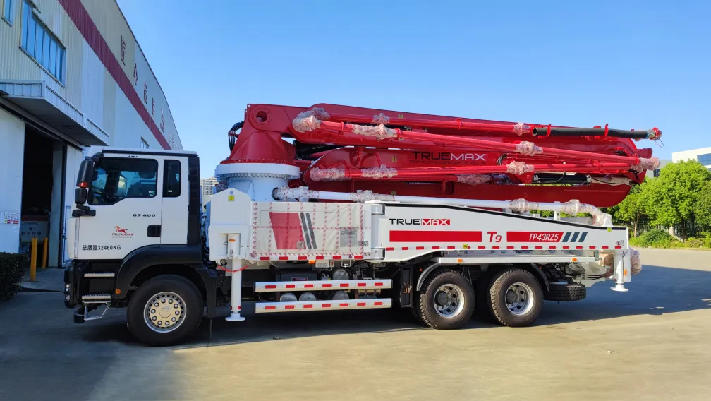
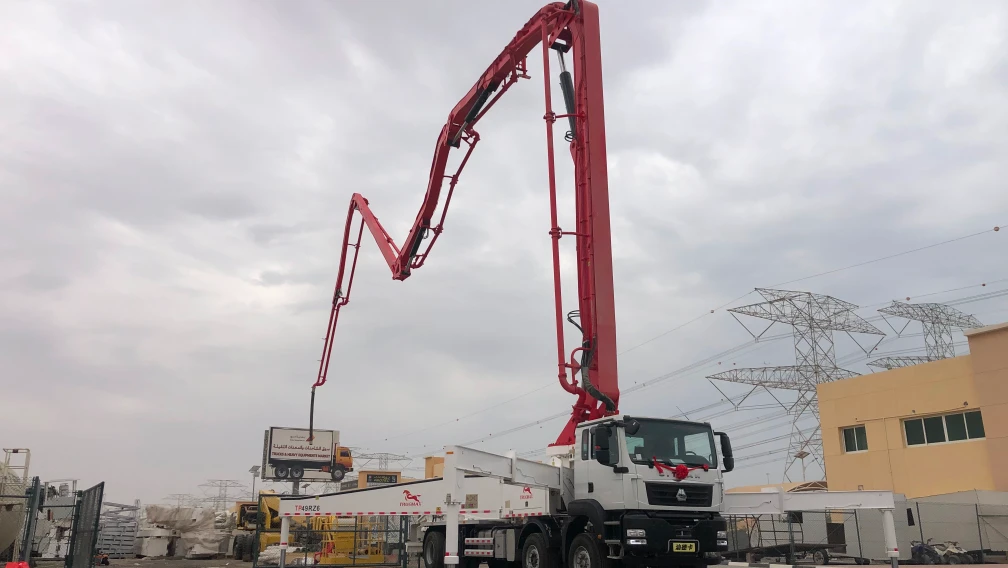
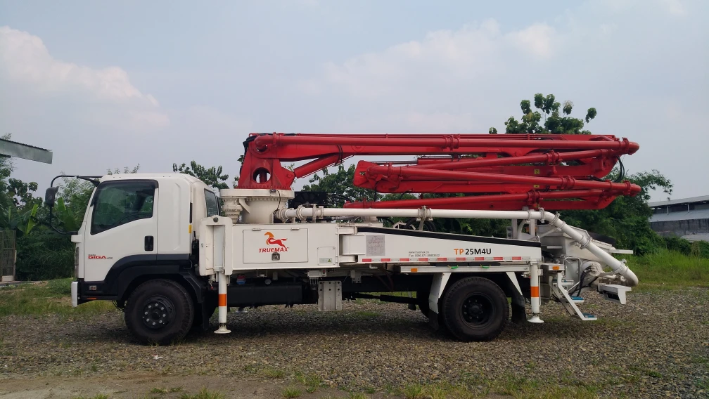
A Truck-Mounted Boom Pump operates as a highly mobile, self-contained concrete placement unit. The system integrates three independent engineering disciplines onto a single commercial truck chassis: a high-pressure hydraulic material pumping group, a multi-section robotic placing boom, and a structural outrigger stabilization frame. Fleet managers procure these units to execute rapid, high-volume concrete pours where ground-line logistics are restricted. The machine arrives, deploys its stabilization legs, unfolds its aerial boom, completes the structural pour, and vacates the site within a single operational window.
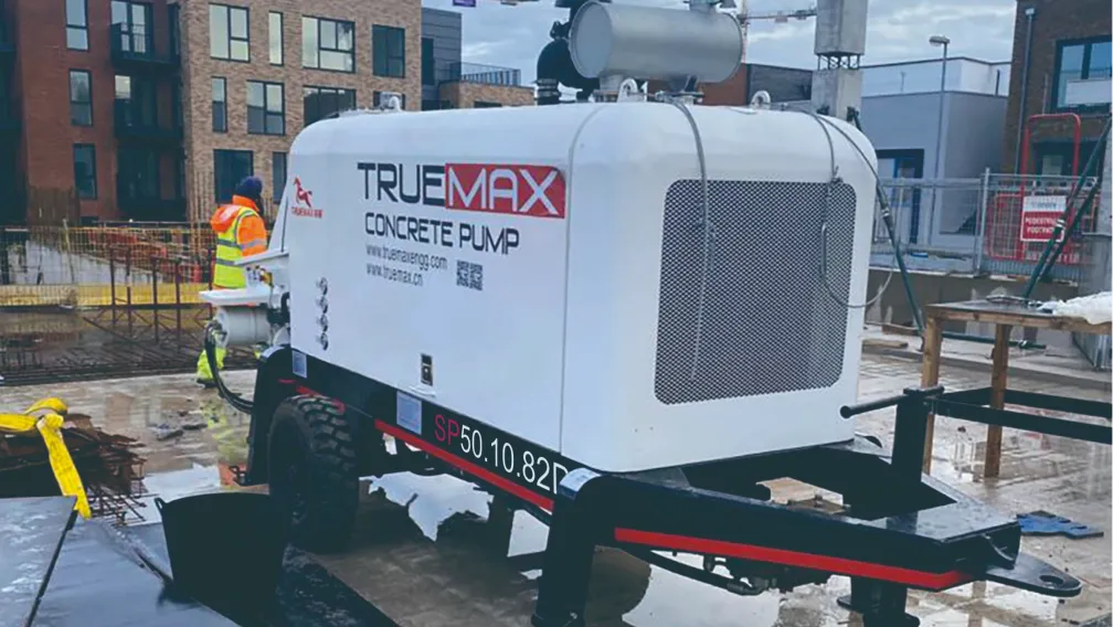
Unlike a Stationary Concrete Pump, which requires manual installation of ground pipelines, the boom pump relies entirely on its articulated mast to bridge the distance between the ready-mix delivery point and the structural formwork. The performance of the unit is defined by its vertical reach (measured in meters), its maximum theoretical concrete output (measured in cubic meters per hour), and the physical footprint required to deploy its outriggers.
2. Boom Articulation Geometries: Z-Fold, R-Fold, and RZ-Fold
The hydraulic boom mast is divided into multiple steel sections linked by articulating hinges. The folding geometry determines how much overhead clearance the machine requires to deploy and how the operator can maneuver the end hose through structural obstacles.
- Z-Fold Geometry: The boom sections fold back and forth upon each other like an accordion. This design requires the lowest unfolding height. An operator can deploy a Z-fold boom entirely inside a warehouse or underneath a bridge deck. When unfolding, the sections drop straight down, allowing the boom to reach deep into excavations or thread through narrow window openings in high-rise construction.
- R-Fold Geometry: Also known as a roll-fold, these sections curl inward in a continuous circular motion. The R-fold design offers excellent structural rigidity and smooth material flow due to fewer sharp angles in the delivery pipe. However, it requires a larger vertical clearance to unfold completely before the operator can extend the mast forward.
- RZ-Fold Geometry: Modern pumps exceeding 40 meters in reach typically utilize a hybrid 5-section or 6-section RZ-fold mast. This configuration combines the high-clearance extension capabilities of the R-fold at the base with the tight-space maneuverability of the Z-fold at the tip.

3. Chassis Selection and Axle Load Distribution
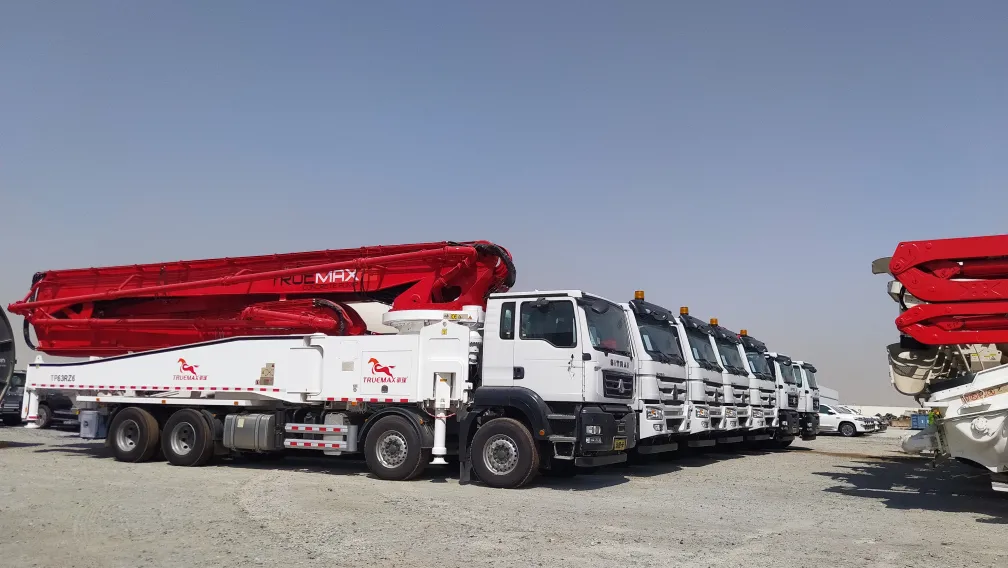
The weight of the boom mast and hydraulic components must comply with regional highway axle load regulations. A 30-meter to 36-meter boom pump typically mounts on a 3-axle truck chassis (6x4 configuration). As reach extends to the 40-meter and 50-meter class, the total machine weight necessitates a 4-axle (8x4) or 5-axle chassis to distribute the load legally across the pavement.
Furthermore, the chassis must comply with local environmental standards, utilizing Euro IV, Euro V, or Euro VI engine configurations complete with AdBlue injection systems. The truck manufacturer and the pump manufacturer must engineer the integration flawlessly so that the pump's sub-frame absorbs the operational torsion without cracking the primary truck chassis rails.
4. Outrigger Stabilization and Ground Bearing Pressure
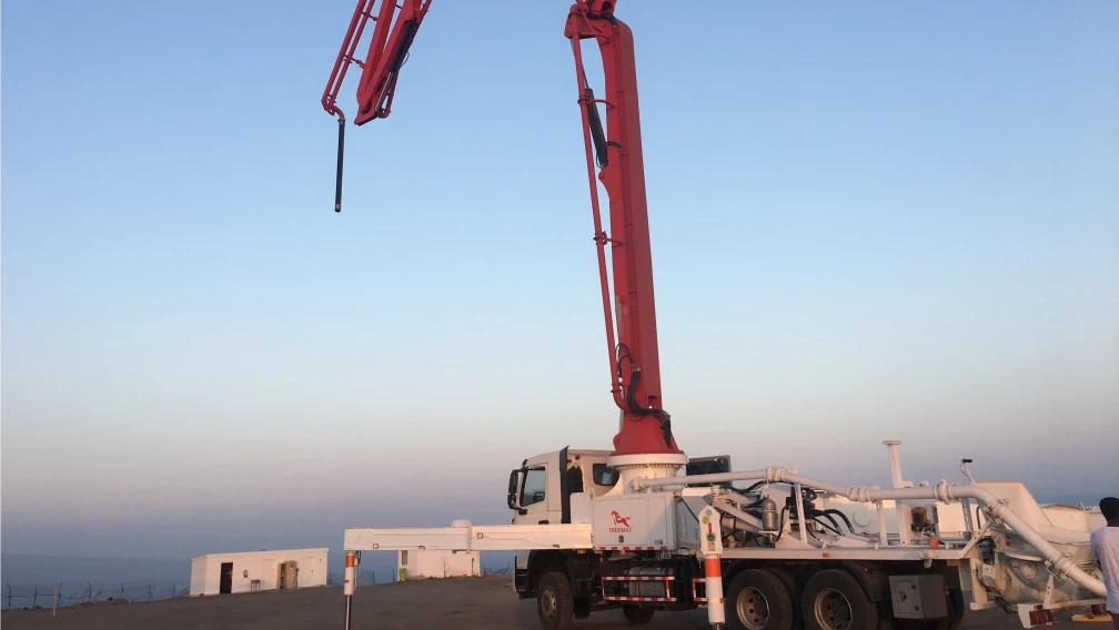
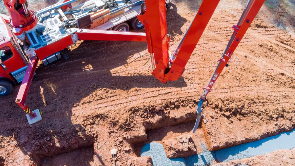
Deploying a heavy steel mast 50 meters into the air shifts the vehicle's center of gravity drastically. To prevent catastrophic tipping, the chassis is equipped with structural outriggers that lift the truck tires off the ground and transfer the total machine weight directly into the soil.
Outrigger configurations generally fall into two categories: X-style (diagonal swing-out) front legs and H-style (telescopic) rear legs. X-style front legs provide an exceptionally wide stance to counteract the lateral torque generated when the boom slews to a 90-degree angle. Ground bearing pressure is a critical jobsite calculation. A standard 47-meter pump transfers enormous point loads through its outrigger pads. Operators must verify that the soil compaction exceeds the machine's maximum outrigger pressure. Soft soil, fresh backfill, or hidden underground utilities require the use of supplementary dunnage (timber mats or steel plates) to distribute the point load over a wider surface area.
For urban jobsites with restricted road widths, modern machines utilize One-Sided Support (OSS) technology. OSS allows the operator to deploy the outriggers fully on the pouring side of the truck while keeping the opposite outriggers retracted within the vehicle footprint. Electronic sensor interlocks communicate with the boom rotation gear, physically preventing the operator from slewing the heavy mast over the unsupported side of the chassis.
5. Core Pumping Hydraulics and the PTO System
The heavy hydraulic flow required to pump 140 cubic meters of concrete per hour is driven by the truck chassis engine. The engine routes mechanical power through a transfer case known as a Power Take-Off (PTO). The PTO splits the engine torque, directing it away from the truck's drive axle and into the main hydraulic axial piston pumps.
Concrete pumping relies on a dual-cylinder hydraulic circuit. As one material cylinder retracts to pull wet concrete from the rear hopper, the other cylinder extends to push concrete into the delivery pipe. The transition between these two cylinders is governed by the S-valve (or S-tube). The S-valve is a cast-steel swinging pipe inside the hopper that snaps back and forth, connecting the active pushing cylinder to the main delivery pipeline.
In an open-loop hydraulic system, the hydraulic oil returns to the main atmospheric tank after completing its stroke before being drawn back into the pump. This setup is simpler to maintain and highly robust against fluid contamination. Conversely, a closed-loop system routes the returning oil directly back into the intake of the main hydraulic pump. This method creates a highly pressurized, rapid-response circuit that operates with a smaller total volume of hydraulic oil. The closed-loop setup reduces the physical size of the oil tank required on the truck deck and provides faster S-valve switching times, which directly reduces the material interruption in the pipeline and minimizes boom bounce.
6. Managing Wear Parts in the Delivery Pipeline
The internal delivery pipeline is subjected to severe abrasive friction. The pipes bolted along the boom structure are generally 125 mm (5 inches) in diameter. Because the concrete is pushed at high velocity, standard single-wall steel pipes wear out quickly, especially at the hinge elbows where the concrete changes direction.
To extend service intervals, manufacturers utilize twin-wall pipe technology. The inner pipe lining consists of heat-treated, high-chromium cast iron designed to withstand the cutting action of sharp silica sand and crushed aggregate. The outer shell is constructed of shatter-resistant structural steel to maintain pressure containment.
At the rear hopper, the spectacle wear plate and the cutting ring form the mechanical seal against the swinging S-valve. These components are reinforced with tungsten carbide inserts. When this seal wears down, pressurized cement paste escapes back into the hopper, causing the aggregate inside the pipe to dry out and form a solid plug. Routine inspection of this clearance gap is mandatory to prevent mid-pour pipeline blockages.

7. Fleet Logistics and Equipment Synchronization
A boom pump provides high-speed placement, but it requires a constant, uninterrupted supply of material. If the supply chain breaks, the concrete sits static inside the aerial pipeline, increasing the risk of premature setting.
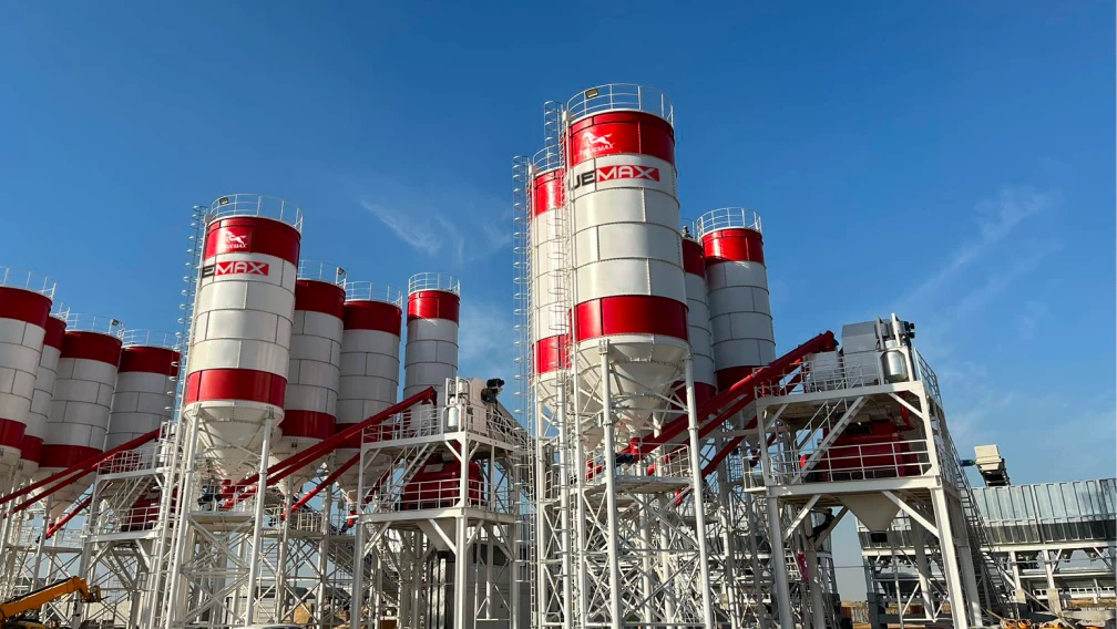
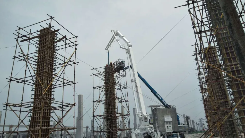
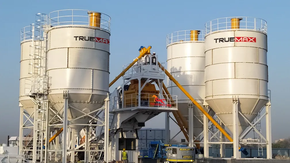
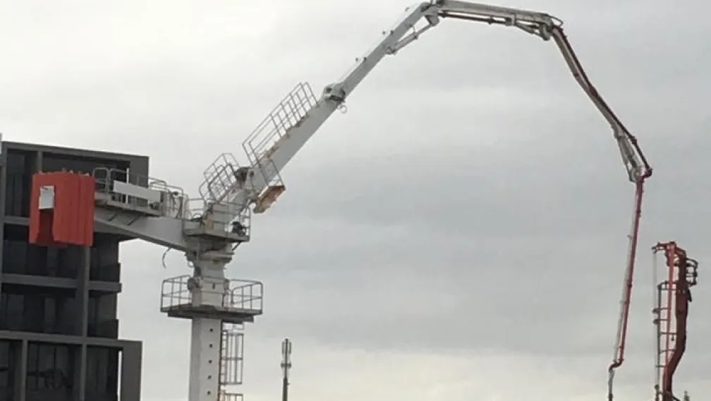
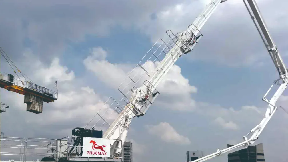
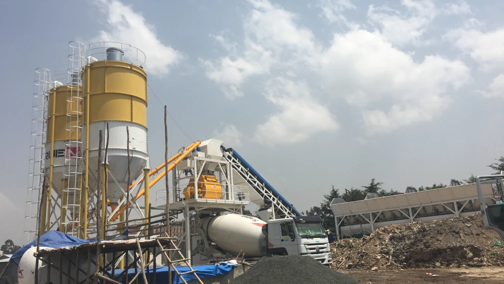
To prevent cold joints on the jobsite, the transit speed of the mixer fleet must match the output capacity of the pump. The local Concrete Batching Plant must adjust its hourly output to sustain the continuous loop. If a specific structural element, such as a high-rise core wall, exceeds the vertical reach limit of the truck-mounted mast, the contractor must demobilize the truck pump and transition to a mechanical Concrete Placing Boom fed by a high-pressure stationary line.
8. Frequently Asked Questions
Q1: What is the maximum safe wind speed for operating a truck-mounted boom pump?
A: Design specifications typically rate structural boom integrity up to wind speeds of 72 km/h (20 m/s). However, for operational safety and precise hose control, most site protocols require the operator to stow the boom when sustained wind speeds exceed 45 km/h. High winds cause severe mast deflection and endanger the placement crew guiding the end hose.
Q2: How does One-Sided Support (OSS) improve jobsite setup?
A: OSS allows a pump truck to set up in confined spaces, such as a single lane of traffic. The outriggers are fully extended on the working side and kept retracted on the street side. The machine's onboard computer restricts the boom's slewing angle (typically a 120-degree to 138-degree working envelope) to ensure the center of gravity never crosses the unsupported side of the chassis.
Q3: What causes the boom mast to bounce during pumping?
A: Boom bounce is a reaction to the sudden hydraulic pressure spikes generated when the S-valve shifts inside the hopper. When the flow of concrete momentarily pauses and restarts, the kinetic energy transfers through the pipeline into the steel mast. Modern systems use electronic dampening valves and accumulator circuits to smooth these pressure transitions and keep the end hose stable.
Q4: What is the lifespan of twin-wall delivery pipes?
A: The lifespan depends entirely on the abrasiveness of the concrete aggregate. With standard river gravel and a highly optimized mix design, twin-wall straight pipes can last between 40,000 to 60,000 cubic meters. Abrasive crushed manufactured sand (M-sand) will significantly reduce this lifespan. Elbows wear out much faster than straight sections and require more frequent replacement.
Q5: Why is the unfolding height a critical specification?
A: The unfolding height determines the minimum vertical clearance required above the truck before the mast can be extended horizontally. A machine with a low unfolding height (such as a Z-fold geometry) can drive inside industrial warehouses or under existing bridges, deploy its boom, and pump concrete without hitting the ceiling structure.
Q6: How do you clear a concrete blockage inside the boom pipeline?
A: The operator must immediately stop the pumping cycle and run the main hydraulic pump in reverse for two to three strokes to relieve the line pressure. The crew then taps along the steel pipeline with a hammer to locate the dull sound of the solid plug. Once the line is fully depressurized, the specific pipe clamp is opened, the dry aggregate is cleared manually, and the joint is re-lubricated with grout before resuming operation.
-

TrueMax
Concrete & Construction Equipment ManufacturerEstablished in 2003, Truemax designs, manufactures, and delivers concrete pumping equipment, crushing machinery, and construction hoisting systems from our own factory in Haining, China to jobsites in over 120 countries.