

 LANGUAGE

1. Why High-Rise Pumping Is a Pressure Engineering Problem
High-rise concrete placement succeeds or fails on pressure control. A ground slab pour is limited mainly by output and truck supply. A tower pour adds a vertical column of concrete that the pump must lift, hold between strokes, and push through bends, reducers, a riser pipeline and the placing boom at the working level. The pump nameplate is only the starting point. The real question is how much pressure remains at the discharge point after static head and friction losses are consumed.
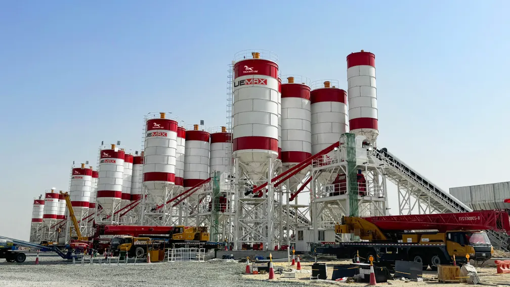
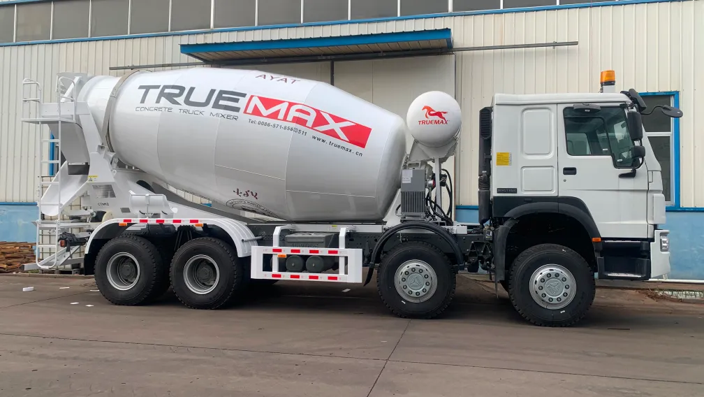
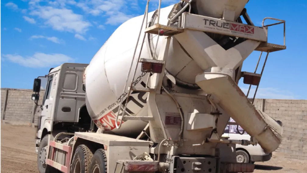
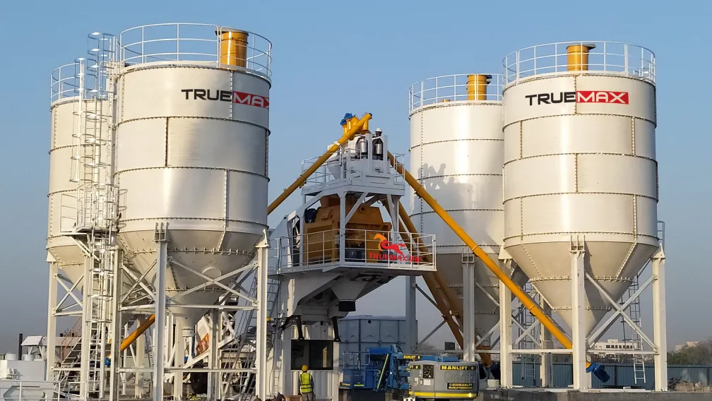
For procurement teams, the correct approach is to treat the stationary concrete pump, riser pipeline, concrete placing boom, batching feed and mixer-truck cycle as one engineered system. A weak clamp, an undersized bend, a poorly graded mix or an unplanned boom position can reduce placing rate even when the pump itself has enough power.
This guide uses planning values drawn from ACI 304.2R-17 practice, EN 12001:2012 safety requirements for placing equipment, and field figures used across TRUEMAX high-rise packages. Final design must be checked against project specifications, local codes and a trial pump where the mix is marginal.
2. Build the Pressure Budget Before Selecting the Pump
Select the pump after the pressure budget is fixed. The budget has four parts: static head, straight-line friction, local losses at bends and fittings, and the internal loss of the placing boom. Use the table below as a first-pass planning basis for DN 125 hardened steel line and a conventional pumpable structural mix.
| Pressure component | Planning value | Design note |
|---|---|---|
| Vertical static head | 0.20–0.25 bar per metre of lift | Fresh concrete at about 2,400 kg/m³ creates roughly 2.0–2.5 bar per 10 m before friction. |
| Horizontal straight pipe | 0.5–1.0 bar per 100 m | Use the higher value for stiff mixes, lower slump, hot weather or worn pipe. |
| Each 90° bend | 1–2 bar | Long-radius bends reduce loss and lower wear at the outer radius. |
| Reducer plus flexible end hose | 2–3 bar combined | Step diameters down gradually; avoid short reducers near the riser base. |
| Placing boom internal pipeline | 5–10 bar | Depends on arm count, bend radius, pipe condition and end-hose movement. |
| Engineering reserve | 30–40% of calculated demand | Covers start-up surges, slump drift, temperature and partial line restriction. |
Worked example: a 180 m residential tower uses a 60 m horizontal lead-in, six 90° bends, one reducer with end hose, and a PB28A-class placing boom. Static head is 36–45 bar. Add 0.3–0.6 bar for horizontal run, 6–12 bar for bends, 2–3 bar for the reducer and hose, and 5–10 bar inside the boom. The calculated demand is about 50–71 bar, or 5.0–7.1 MPa. With a 30–40% reserve, the pump should be specified around 7–10 MPa for normal operation, with higher pressure available for restart after a delay or for a stiffer mix. This is why high-rise packages commonly use the 18–25 MPa class rather than a pump selected only by output.
Equivalent Horizontal Pumping Distance is useful for early screening: add the horizontal run to roughly four to five times the vertical lift, then add bend equivalents. Use it to compare layouts. Do not use it to replace a pressure budget when the pour height, mix class or pipe diameter changes.
3. Riser Pipeline Design and Structural Anchoring
The riser is a pressure-bearing structure, not a temporary hose run. Use hardened seamless steel pipe with wall thickness, clamps, gaskets and wear sleeves rated above the pump’s maximum working pressure. DN 125 is common for high-rise work because it balances pressure loss, line weight and placement control. DN 150 reduces friction for high output but adds mass and is less forgiving at tight floor openings.
Base layout
Start the riser with a horizontal lead-in before the first vertical bend. This straight section absorbs pulsation from the S-valve and gives the operator a stable zone for priming, sampling and blockage clearance. Keep the first vertical bend long-radius and brace it independently. Avoid mounting the first bend directly at the pump outlet.
Anchoring and floor penetrations
Anchor the riser to the structure at every floor or at engineered intervals approved by the project structural engineer. The anchors carry line weight, thermal movement and the reaction force from each pumping stroke. At floor penetrations, use sleeves that allow alignment correction without forcing the pipe into a bind. A misaligned riser increases local wear and creates a blockage point at the first stiff batch.
Bends, reducers and inspection points
Keep the bend count low. Where a change of direction is unavoidable, use long-radius hardened bends and log their pumped volume. Install reducers away from high-turbulence zones where possible, and never bury a reducer inside a congested reinforcement cage. Provide inspection and cleanout access at the riser base, at the working-level connection and at any point where the line diameter changes.
4. Matching Pump, Riser and Placing Boom as One System
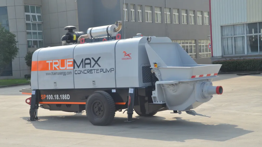
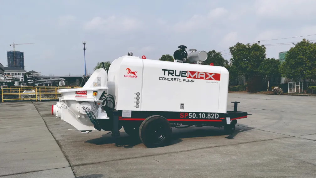
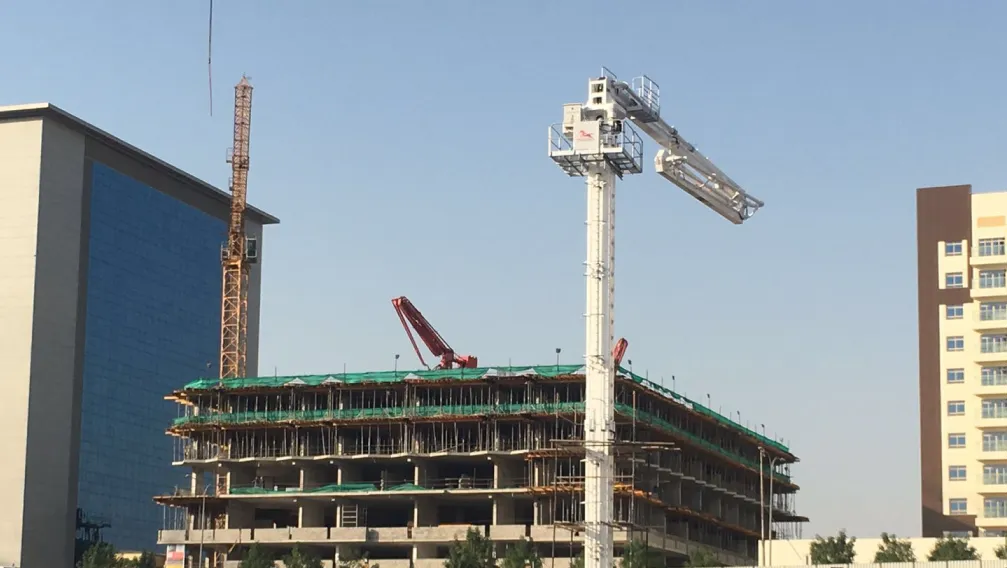
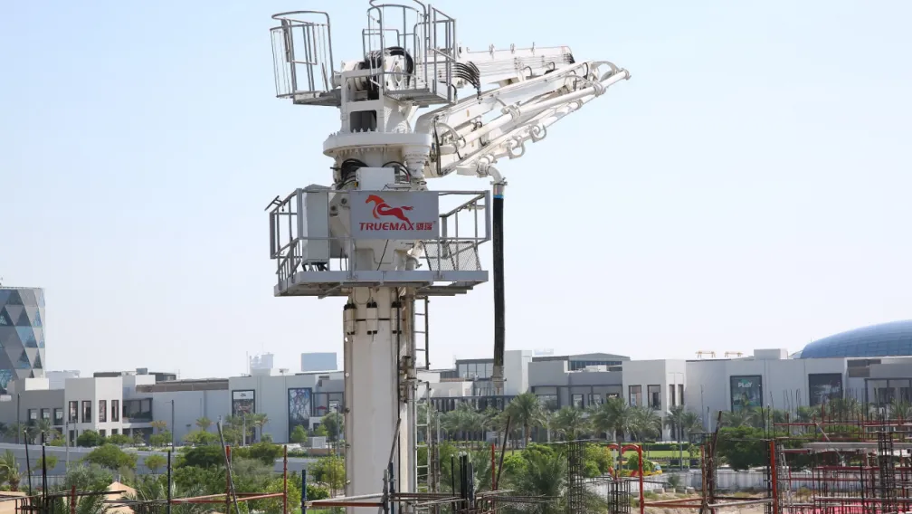
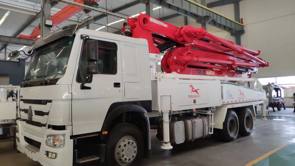
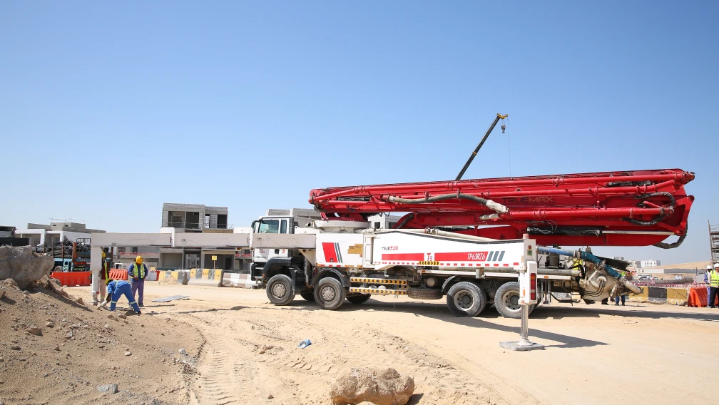
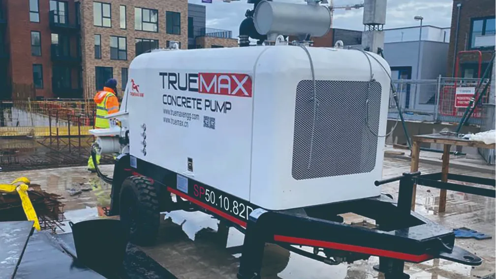
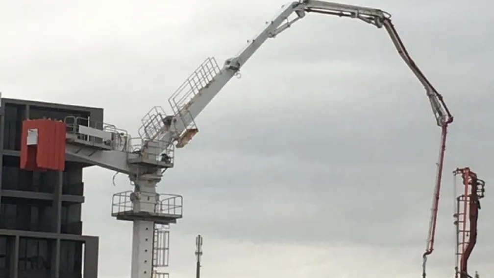
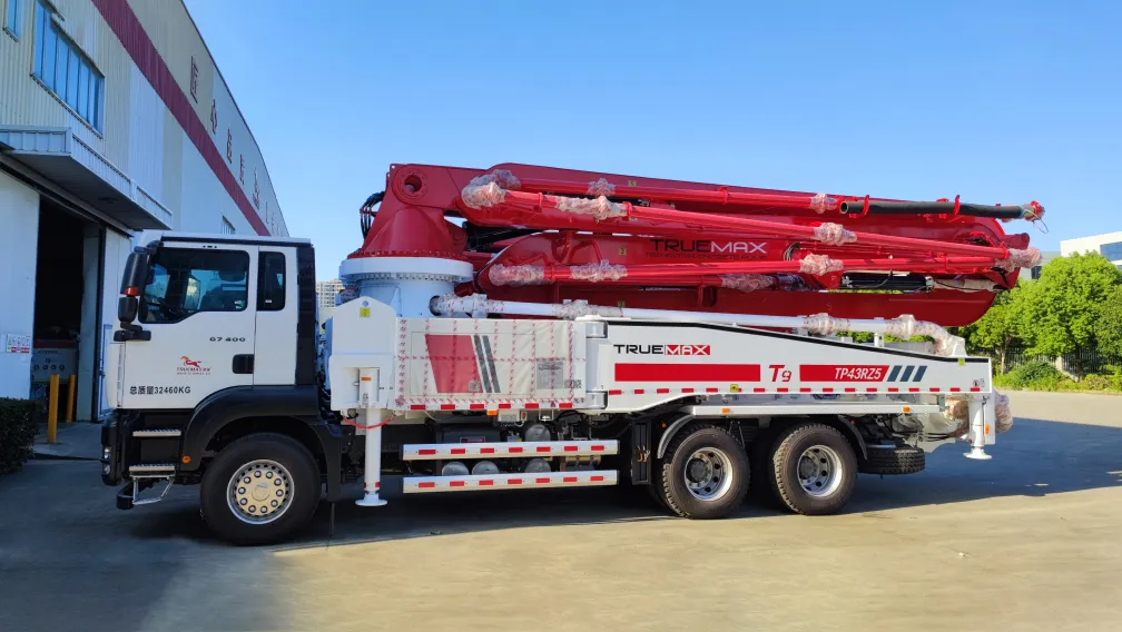
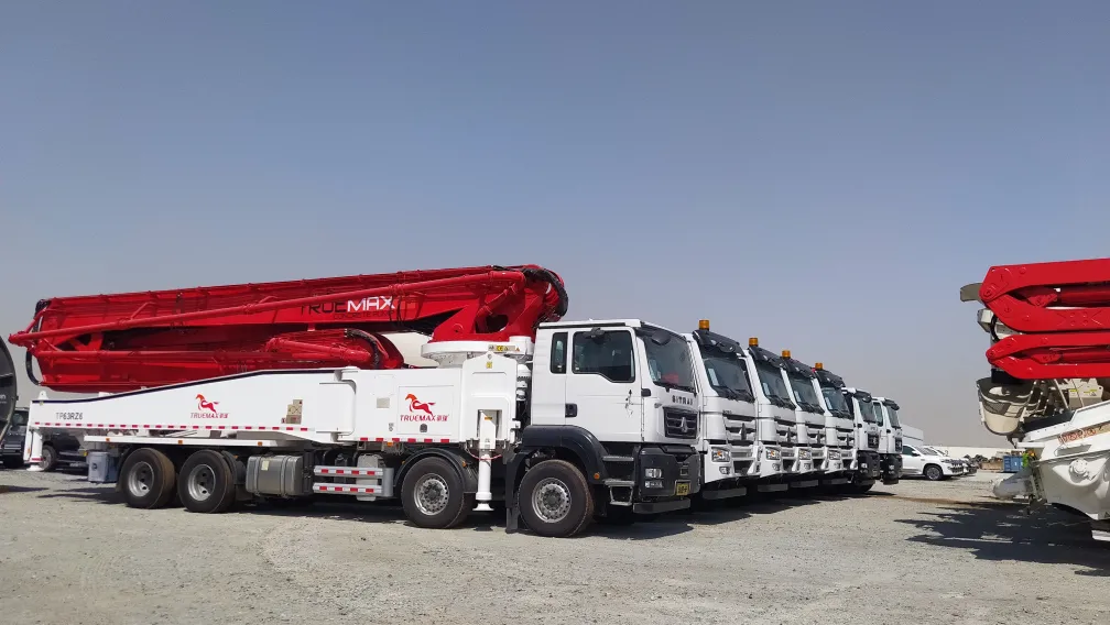
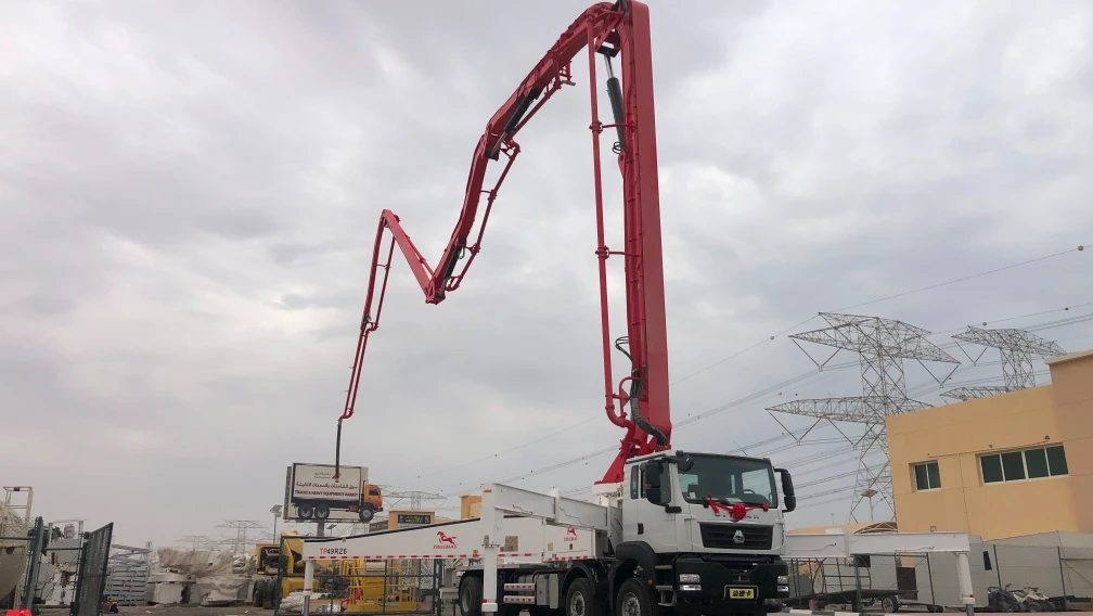
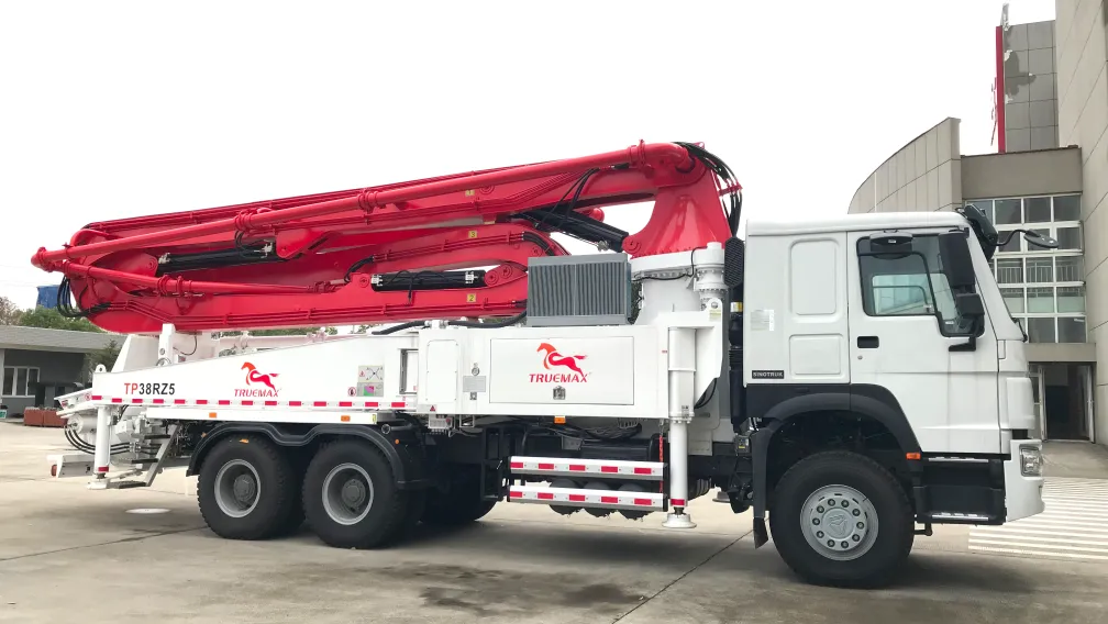
High-rise placement normally uses a high-pressure stationary pump at ground level, a fixed riser, and a placing boom on the working floor. A truck-mounted boom pump remains the fastest tool for podium levels and open pours within its reach. Once the structure exceeds practical boom reach, the stationary pump plus riser plus placing boom package gives better pressure control and keeps the concrete path inside the building footprint.
Pump selection starts with required placing rate in m³/h, then checks pressure. A 100 m³/h class pump is only useful if the batching plant, truck cycle and placing crew can sustain that rate. If the pour plan is 45–60 m³/h, specify the pump for pressure margin and steady low-speed control rather than maximum theoretical output. The S-valve must seal cleanly at high pressure so the column does not fall back between strokes; worn cutting rings and spectacle plates show up first as pressure pulsation and reduced vertical reach.
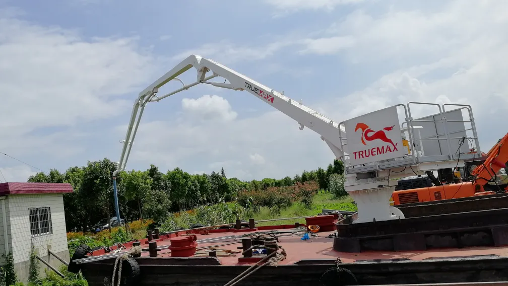
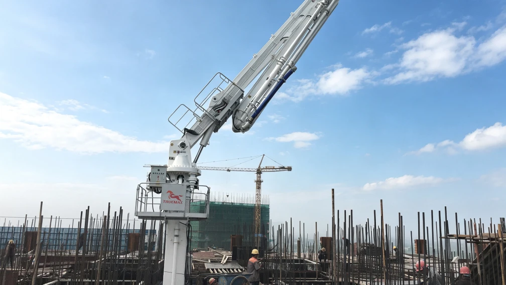
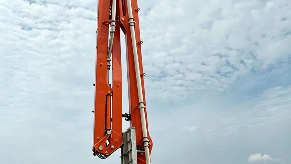
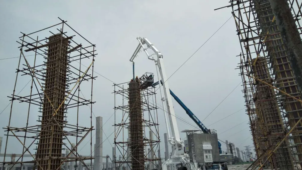
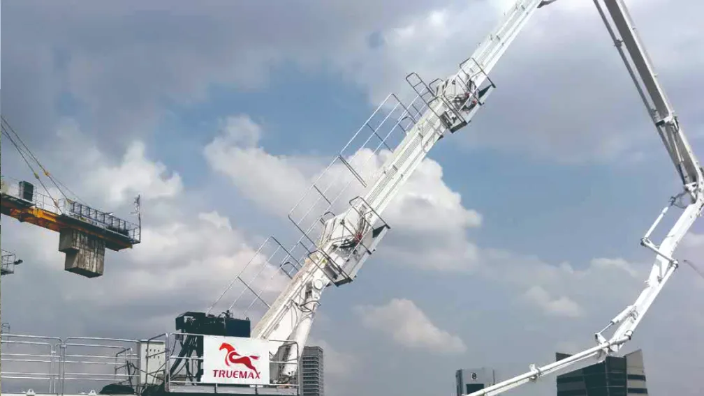
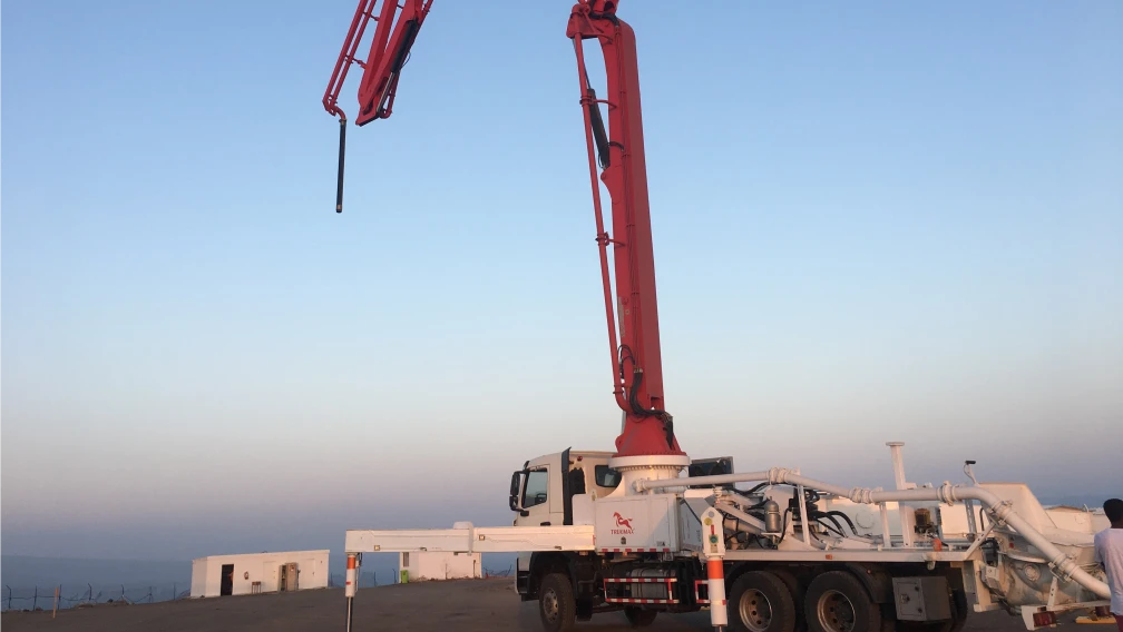
The placing boom radius must cover the pour from approved set-up points. Model numbers are based on placing radius, so a PB28A-class boom covers about 28 m. On large floor plates, plan multiple boom positions or a climbing sequence rather than stretching the end hose beyond safe handling. Confirm whether the building supports a column-climbing boom, whether jump-form integration is required, or whether a spider boom will be lifted by tower crane between floors. The choice changes riser connection details, floor loading and cycle time.
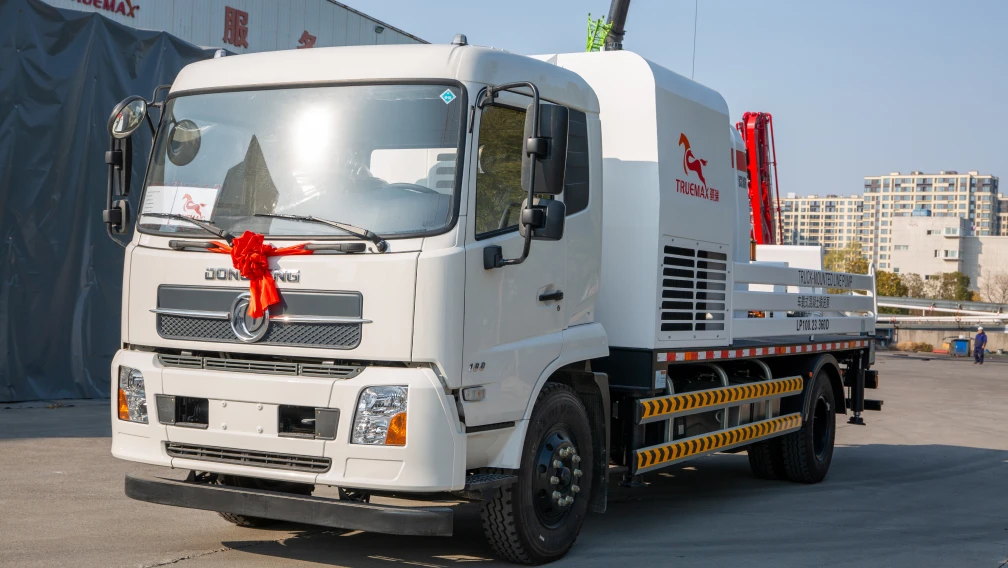
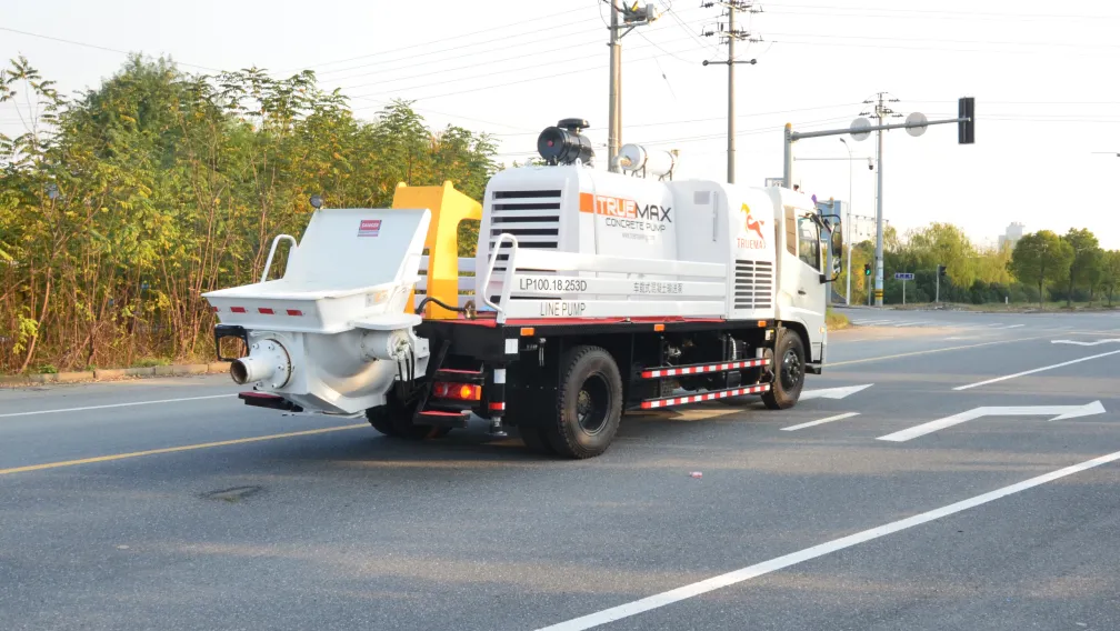
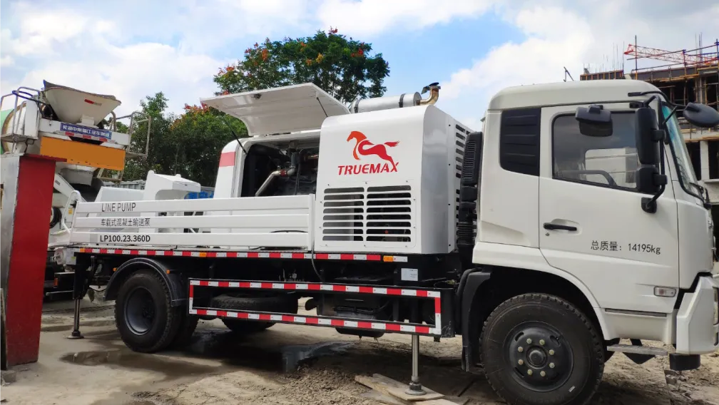
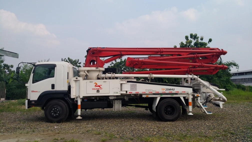
For open lower levels, a truck-mounted line pump can feed temporary lines to foundations, transfer slabs and podium decks. On congested city sites this avoids tying up a boom pump. For permanent vertical work, transfer the same pumping logic to the fixed riser and placing boom once the structural cycle begins.
5. Concrete Mix Design for Vertical Pumping
ACI 304.2R-17 remains the reference for pumped placement. For high-rise work, the mix must stay cohesive under pressure and after restart. Use a water-binder ratio suited to the strength class, commonly 0.30–0.50, with 0.30–0.40 for high-strength vertical pumping. Keep slump in the 100–180 mm working window unless the project specifies self-consolidating concrete, and design for slump retention across the full haul, waiting and placing period.
Aggregate grading controls friction. Follow ASTM C33/C33M or the local equivalent, keep maximum aggregate size at or below one-third of the smallest internal pipe diameter, and use continuous grading rather than gap grading. Maintain enough fine material passing 300 µm and 150 µm so the mix forms a lubricating layer at the pipe wall. Fly ash at 15–25% replacement and GGBS at 30–50% can improve flow and reduce line friction when strength and durability requirements allow. Polycarboxylate superplasticisers are standard for high-rise and low water-binder mixes; dose for retention, not only initial slump.
Trial-pump marginal mixes through a line that reproduces the project’s vertical height, bend count and hose arrangement. A laboratory slump test alone does not prove pumpability. Record pressure at the pump outlet, discharge consistency, bleed, segregation and restart behaviour after a 20–30 minute stop.
6. Commissioning, Testing and Daily Operating Controls
Before the first structural pour, pressure-test the assembled riser as a system. Inspect clamps, gaskets, bend wear sleeves, anchor bolts and the working-level connection. Verify that the placing boom interlocks, radio remote and cable backup operate correctly under load. EN 12001:2012 and ISO 21573-1/2 provide the safety and test framework; local regulations and the project lift plan still govern.
Prime the line with cement slurry or approved priming grout before concrete enters the riser. Purge air pockets, start at reduced output, and bring the pump up to rate only after discharge stabilises. If pressure rises abnormally, reverse the pump to draw the plug back toward the hopper; forcing a blockage forward compacts the plug and increases the risk of a blow-out at a weak fitting.
Track consumables against pumped volume. Cutting rings, spectacle plates, chrome-plated delivery cylinders, bend sleeves and end hoses should have inspection limits and replacement stock on site. Wash out with a sponge ball driven by water or air at the end of the pour, then clean the hopper, S-tube and water box before paste hardens. Remote diagnostics and hour logging help maintenance teams spot pressure drift before it becomes a stoppage.
7. Frequently Asked Questions
Q1: What pump pressure is required for a 200 m high-rise riser?
A: Start with static head at 0.20–0.25 bar per metre, which gives 40–50 bar for 200 m before friction. Add straight-line loss, bends, reducers, end hose and placing-boom internal loss, then apply a 30–40% reserve. Most projects specify an 18–25 MPa class pump to keep operating pressure well below the machine ceiling and to retain restart capacity after delays.
Q2: Can a truck-mounted boom pump handle a full high-rise tower?
A: A boom pump is efficient for podium levels, lower floors and open pours within its vertical reach. Above practical boom reach, contractors switch to a stationary high-pressure pump feeding a fixed riser and a placing boom on the working floor. This keeps pressure controllable and avoids extending temporary hose inside the structure.
Q3: Why does the riser need a horizontal lead-in before the vertical climb?
A: The horizontal lead-in absorbs S-valve pulsation and stabilises flow before the concrete enters the vertical column. It also creates a safer location for priming, sampling and clearing a restriction. Starting the climb immediately at the pump outlet raises turbulence and makes the first bend a high-wear, high-risk point.
Q4: What causes a high-rise line to block after a short stop?
A: The usual causes are slump loss, bleed-water separation, insufficient fines, excessive aggregate size for the pipe diameter, and heat build-up during waiting. A mix that pumps at batching can still segregate after a delay if retention and cohesion were not designed for the full cycle. Trial pumping with timed stops is the reliable check.
Q5: How often should riser bends and clamps be inspected?
A: Inspect clamps, gaskets and anchors daily during active pouring. Log pumped volume through each bend and compare wall thickness or wear-sleeve condition against the manufacturer’s limit. High-wear bends near the riser base and working-level connection normally reach their limit first because turbulence and direction change concentrate abrasion there.
Q6: When should a placing boom climb instead of being lifted by crane?
A: Use a column-climbing or formwork-climbing boom when the floor cycle is repetitive and the structure provides approved anchorage. Use a spider boom lifted by tower crane when floor plates change often, anchorage is limited, or the pour sequence does not justify a climbing mast. The decision affects cycle time, floor loading and riser connection design.
8. High-Rise Pumping Package Consultation
High-rise pumping performance depends on system matching: pump pressure class, riser layout, placing boom radius, batching output, mixer-truck cycle and mix design must be engineered together. TRUEMAX has supplied concrete equipment packages to projects in more than 120 countries since 2003, with boom structures built from ≥900 MPa high-strength steel, 100% weld NDT, CE and ISO 9001:2015 certification, and service teams across the Middle East, Africa and Southeast Asia. Send your tower height, floor plate, target pour rate, mix class and site constraints to the engineering team through the contact page to receive a pump, riser and placing boom configuration proposal within 24 hours.
-

TrueMax
Concrete & Construction Equipment ManufacturerEstablished in 2003, Truemax designs, manufactures, and delivers concrete pumping equipment, crushing machinery, and construction hoisting systems from our own factory in Haining, China to jobsites in over 120 countries.